Ni-P + SiC · silicon carbide composite process · composite plating system
SiC composite electroless nickel
Hard silicon carbide particles are co-deposited in a Ni-P matrix to enhance the wear resistance of working surfaces.
SiC particles to strengthen wear-resistant surfaces.
From production machinery to molds and textile machinery, choose a composite coating around actual contact and wear conditions.
 Click to enlarge ⤢
Selection focus: contact material · load · motion speed · lubrication conditions
01 / COMPOSITE COATING
Matrix and particles, each doing their part.
SiC particles are incorporated into the Ni-P coating for wear conditions; consider both the workpiece and the counterpart material when selecting.
SiC particles enhance wear resistance
The silicon carbide composite process technical data links SiC to wear resistance needs. Wear effect must be evaluated with the counterpart material, particle wear, load and surface condition.
Continuous replenishment to sustain composite plating production
The data states that this system supports continuous composite plating, automatic analysis and replenishment. Bath management and dispersion must follow the corresponding operating documents.
Test charts & test conditions
See wear comparisons including Ni-P / SiC. The oil-fed reciprocating test and the abrasive wear test are listed separately and their conditions cannot be mixed; click a chart to enlarge.
Oil-fed reciprocating wear: coating and counterpart wear
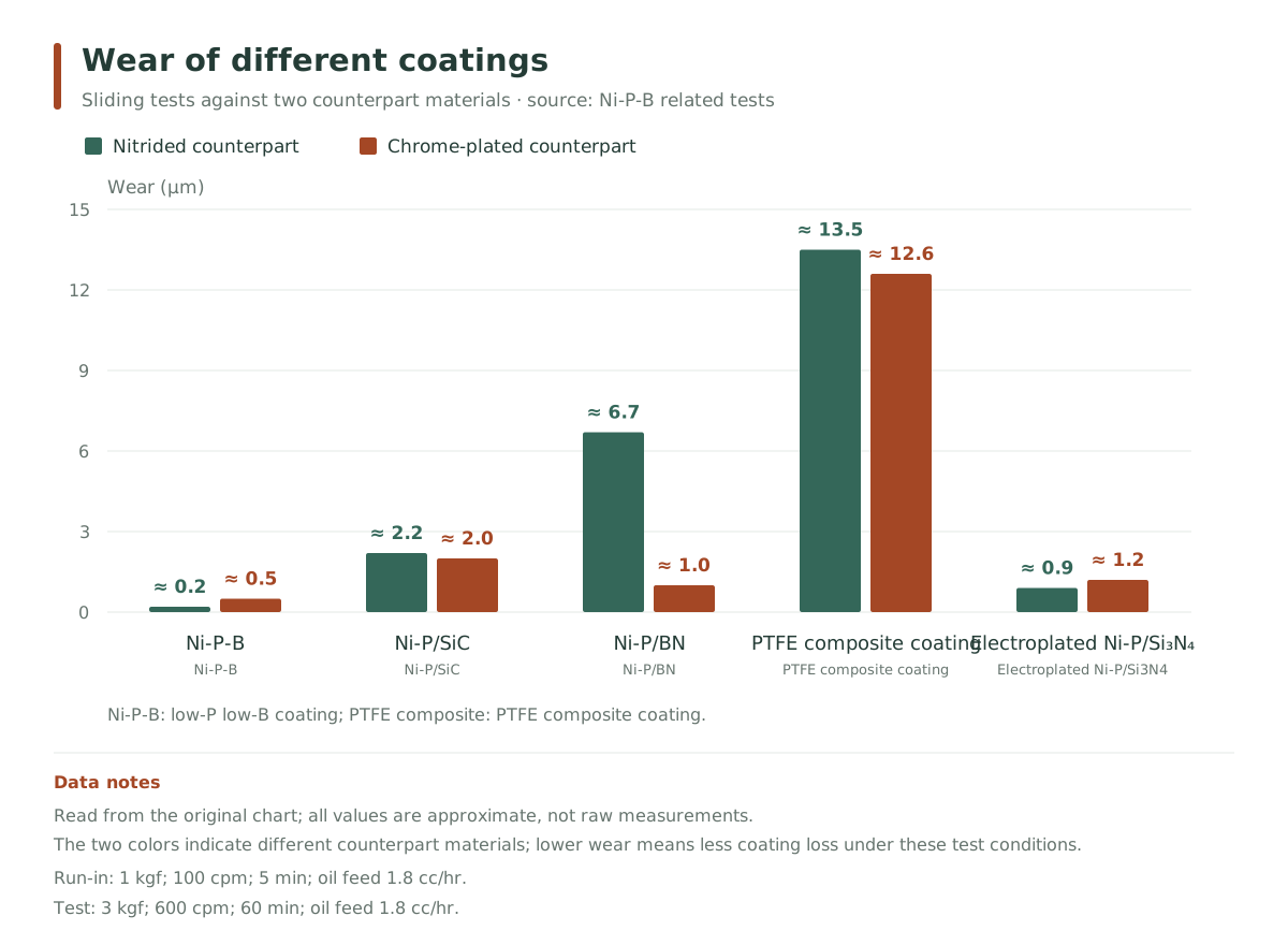
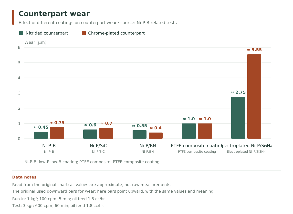
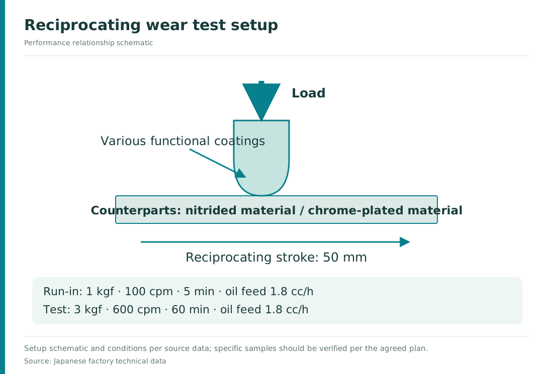
Test method & conditions
- Running-in stage
- 1 kgf;100 cpm;5 min
- Main test
- 3 kgf;600 cpm;60 min
- Oil feed in both stages
- Both 1.8 cc/h
- Counterpart treatment
- Nitriding / chrome plating
Japanese factory test values, not guaranteed values. Bar lengths are read from the original charts. The two result charts show coating wear and counterpart wear respectively; this group's conditions are used on their own.
Abrasive wear test with hard chrome comparison
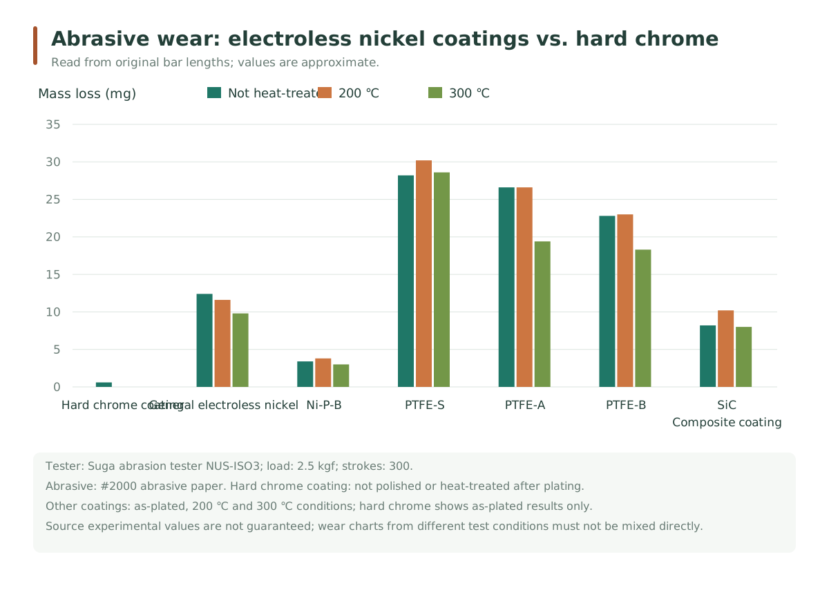
Test method & conditions
- Standard cited by source
- JIS H 8503 (as cited by source)
- Test equipment
- Suga NUS-ISO3 (as labeled in source chart)
- Load / reciprocations
- 2.5 kgf / 300 cycles
- Abrasive
- #2000 abrasive paper
- Hard chrome specimen
- Not ground after plating; not heat-treated
- Other coating conditions
- Not heat-treated / 200 ℃ / 300 ℃
Japanese factory test values, not guaranteed values. Bar lengths are estimated from the original chart. This 2.5 kgf test group must use the above conditions and is compared separately from other temperature–wear tests.
02 / APPLICATIONS
Match the working surface around wear.
Describe where wear occurs, the contact material, load and motion to help judge whether a particle composite coating is suitable.
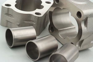 Click to enlarge ⤢
Image from company technical data
- Production machinery
- Metal working surfaces in sliding and frictional contact; evaluate wear needs with contact pressure, motion speed and lubrication method.
- Various molds
- Working surfaces under repeated contact and friction; confirm contact material, operating temperature and critical dimensions.
- Textile machinery
- Metal contact areas in continuous operation; key points to confirm are wear mode, counterpart material and surface roughness.
03 / BATH & PROCESS
Silicon carbide composite process · operating parameters
Source is the formal operating conditions table in the technical data. Deposition rate is process data for estimating production takt.
- Operating temperature
- 85–95 ℃
- pH
- 4.85 ± 0.10
- Deposition rate
- 12 ± 2 μm/h · at make-up, 85 ℃
- Bath load ratio
- 8–12 cm³/cm²
See nickel concentration & composite system notes
| Item | Parameters & conditions |
|---|---|
| Nickel sulfate | NiSO₄·6H₂O:22.5 ± 1.0 g/L |
| Metallic nickel | 5.0 ± 0.3 g/L |
| Dispersion system | The original instructions cover SiC or BN. SiC is for wear resistance and BN for lubrication; they must be selected separately. |
| Particle content | The dispersion ratio at make-up is not the particle content in the coating. Actual co-deposition must be confirmed by the corresponding test. |
| Performance verification | Hardness, wear and life are verified by the selected process, thickness and actual counterpart conditions; the Japanese data below is only a reference for the corresponding coating. |
Source: silicon carbide composite process technical data, pp.3 and 5. The equipment and management sections list other control ranges; make-up and replenishment follow the full TDS.
04 / TECHNICAL IMAGES
View the coating and particles in large images.
Uses original images from the Japanese technical PDF with microscope scale bars kept; particle sizes and material names are set separately.
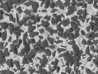
Micrograph extracted directly from the "Silicon carbide composite coating technical data", keeping the original 10 μm scale bar and ×1000 label.
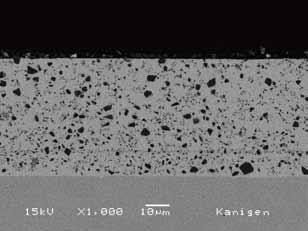 Click to enlarge ⤢
Micrographs are for technical reference; judge size by the scale bar in the image, as displayed magnification varies with screen.
Composite particle structure reference
Two SiC particles compared with Al₂O₃; particle sizes and shapes per original labels.
 Click to enlarge ⤢
 Click to enlarge ⤢
 Click to enlarge ⤢
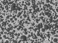
Source: original micrographs of the Japanese silicon carbide composite electroless nickel. Particle sizes and shapes per the data's labels; Al₂O₃ is a reference material; images are not to the same scale for particle size comparison.
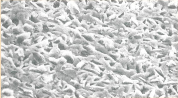
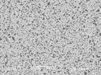
Click to enlarge ⤢Coating surface morphology from the Japanese silicon carbide composite electroless nickel data; original magnification marked as 2500×.
Hardness varies with treatment state
| State | Hardness reference (HV) | Conditions given in the data |
|---|---|---|
| As-deposited | 550–650 | Co-deposited SiC particles |
| After heat treatment | 900–1200 | 300 ℃, 1 hour |
Source: "Silicon carbide composite coating technical data" p.1. This is a SiC coating reference from Japanese data, not an acceptance criterion for the current silicon carbide composite process; hardness acceptance must separately agree specimen, thickness and test load.
Click to enlarge ⤢Application image from the original company product system.
Enlarge ↗Tell us the service conditions and let's confirm the coating together.
For processing evaluation, please provide substrate, key dimensions, friction pair and service environment; for chemical selection, please add tank size, current process and production takt.
Source: "Silicon carbide composite process" technical data, pp.3 and 5; company product data ↗; micrographs and treatment state refer to Japanese silicon carbide composite electroless nickel data and Japanese introduction (printed p.11). Updated 2026-09-20.
Performance is reference data; the specific process, substrate, thickness and test conditions together determine final performance, and acceptance requirements are confirmed per part.