Ni-P-B · nickel-phosphorus-boron process
Electroless Ni-P-B plating
High hardness, even without heat treatment.
Combining the properties of Ni-P and Ni-B for precision parts that need as-plated hardness, wear resistance and impact resistance.
As-deposited hardness
Hardness reference achievable without heat treatment
As-deposited reference value from the Ni-P-B process technical data; acceptance follows the load, thickness and measurement points agreed for the workpiece.
01 / COATING PERFORMANCE
Beyond hardness, built for real use.
A low-P, low-B nickel-based alloy coating combining properties of Ni-P and Ni-B systems.
As-plated hardness & wear resistance
As-deposited hardness ≥700 HV. Suits parts concerned with wear of sliding areas that want to reduce heat treatment steps.
Uniform coating & precision fit
The technical data describes a uniform coating suitable for parts with tight fit requirements; thickness and tolerances are confirmed per the actual structure.
Impact resistant, with functional properties
The data lists impact resistance, heat resistance, solderability and conductivity. Specific temperature and electrical specifications must be verified per operating conditions.
Hardness data comes from p.2 of the Ni-P-B process technical data as an as-deposited reference value, not a guaranteed value for any workpiece. Acceptance hardness must be agreed together with thickness, test load and measurement points.
Test charts & test conditions
Compare friction and wear of Ni-P-B against other coatings. Each chart uses a different test method, with standards and conditions listed under it; click a chart to enlarge.
SRV oil lubrication: friction coefficient & wear depth
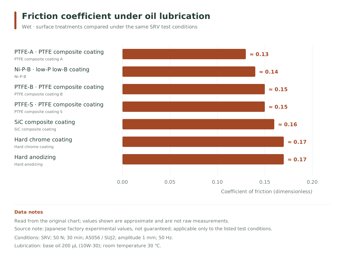
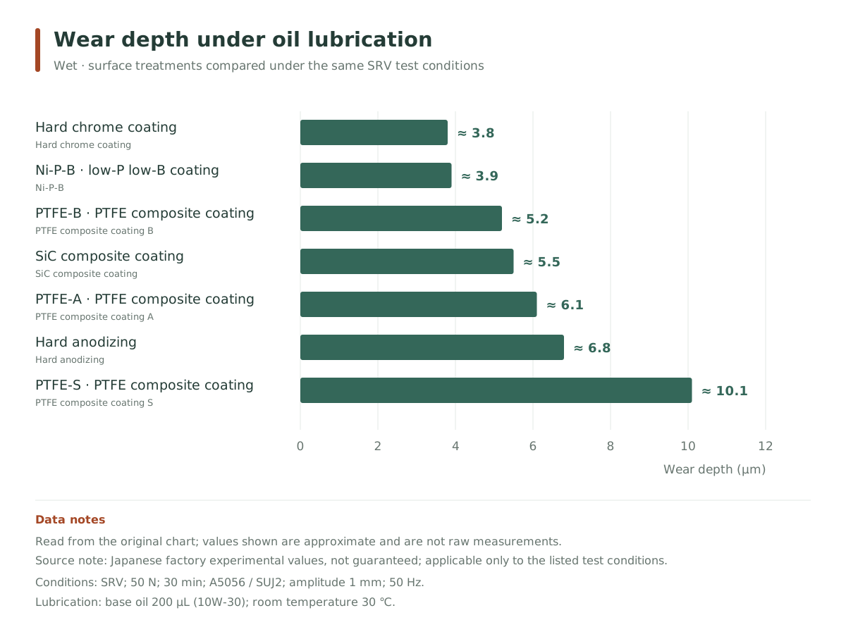
Test method & conditions
- Test equipment
- SRV
- Test equipment
- SRV
- Load / frequency
- 50 N / 50 Hz
- Time / amplitude
- 30 min / 1 mm
- Coated substrate / counterpart
- A5056 / SUJ2
- Lubricant
- 10W-30 base oil, 200 μL
- Temperature
- Room temperature 30 ℃
Japanese factory test values, not guaranteed values. Bar lengths are read from the original charts and values are approximate; they apply only to the listed test conditions.
Oil-fed reciprocating wear: coating and counterpart wear
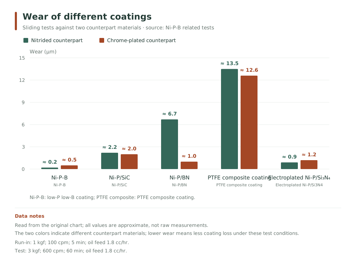
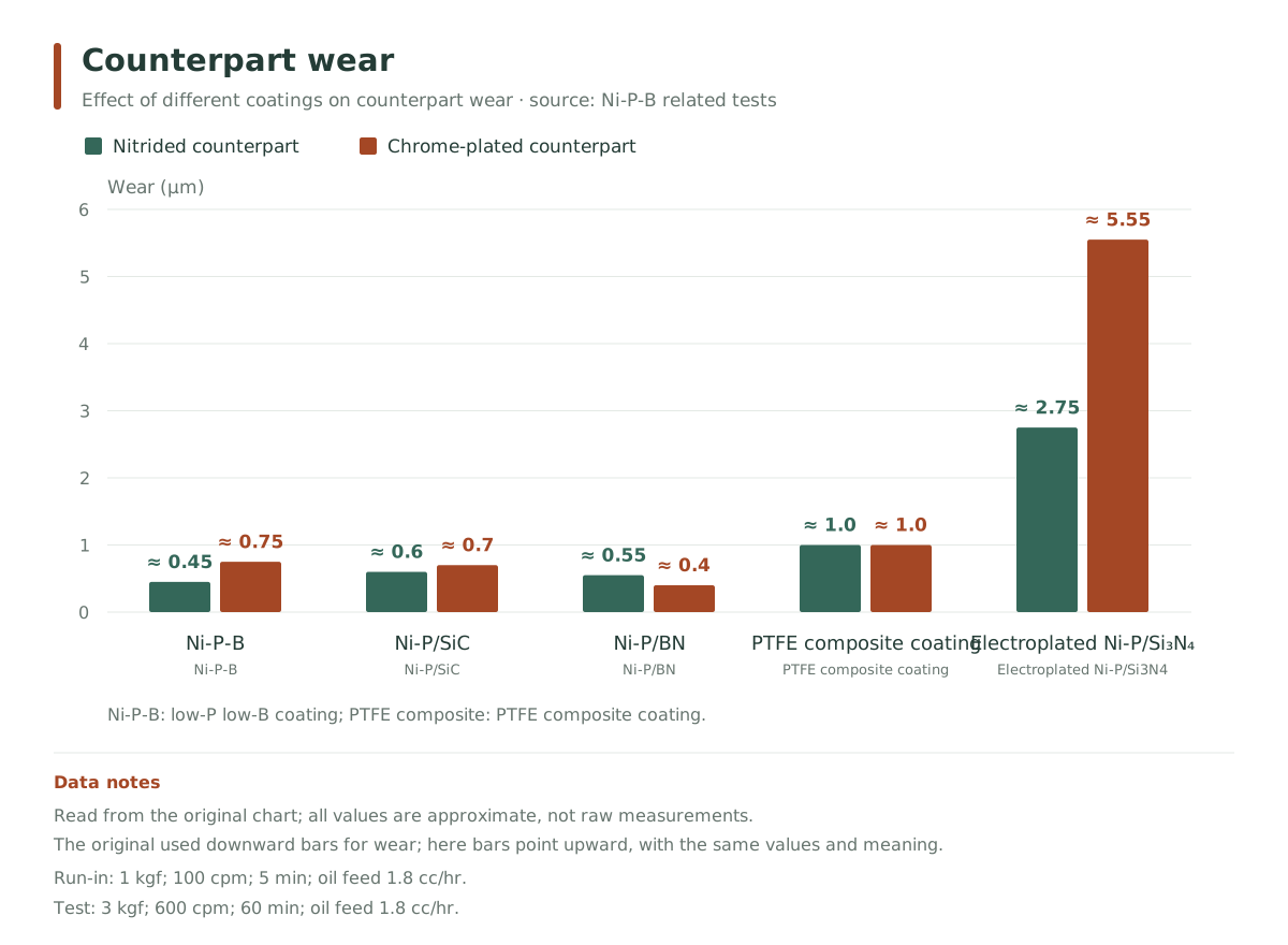
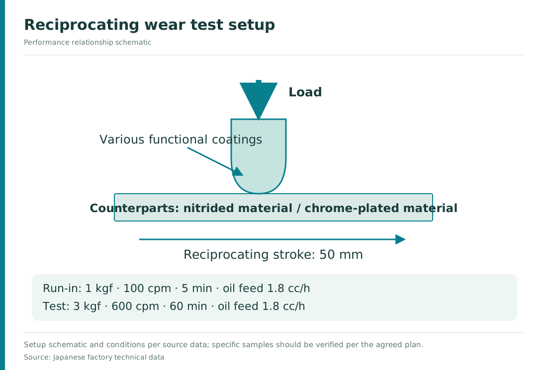
Test method & conditions
- Running-in stage
- 1 kgf;100 cpm;5 min
- Main test
- 3 kgf;600 cpm;60 min
- Oil feed in both stages
- Both 1.8 cc/h
- Counterpart treatment
- Nitriding / chrome plating
Japanese factory test values, not guaranteed values. Bar lengths are read from the original charts. The two result charts show coating wear and counterpart wear respectively; this group's conditions are used on their own.
Abrasive wear test with hard chrome comparison
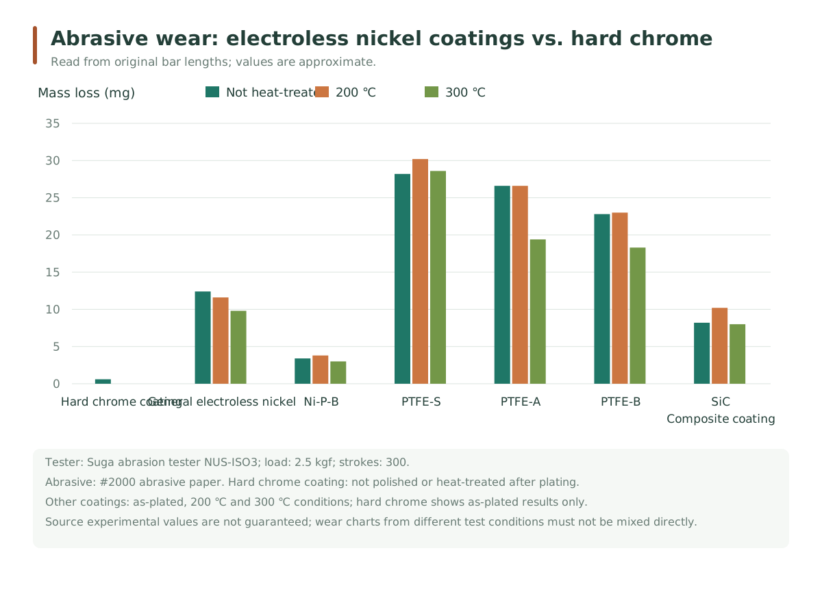
Test method & conditions
- Standard cited by source
- JIS H 8503
- Test equipment
- Suga NUS-ISO3 (as labeled in source chart)
- Load / reciprocations
- 2.5 kgf / 300 cycles
- Abrasive
- #2000 abrasive paper
- Hard chrome specimen
- Not ground after plating; not heat-treated
- Other coating conditions
- Not heat-treated / 200 ℃ / 300 ℃
Japanese factory test values, not guaranteed values. Bar lengths are estimated from the original chart. This 2.5 kgf test group must use the above conditions and is compared separately from other temperature–wear tests.
Ni-P-B hardness & wear reference curves
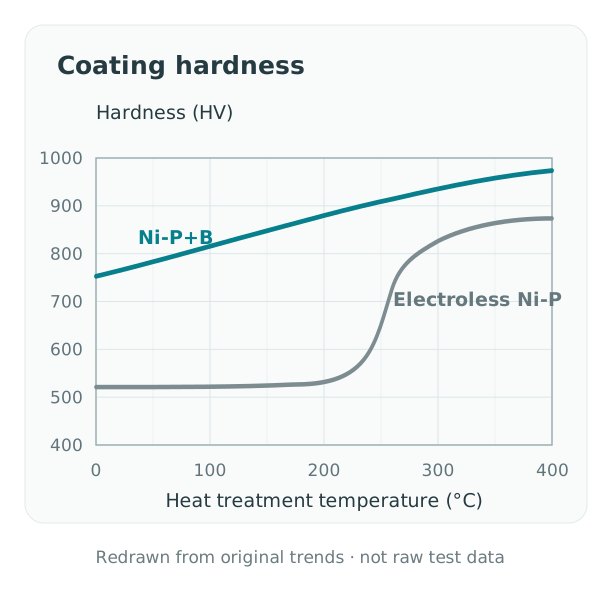
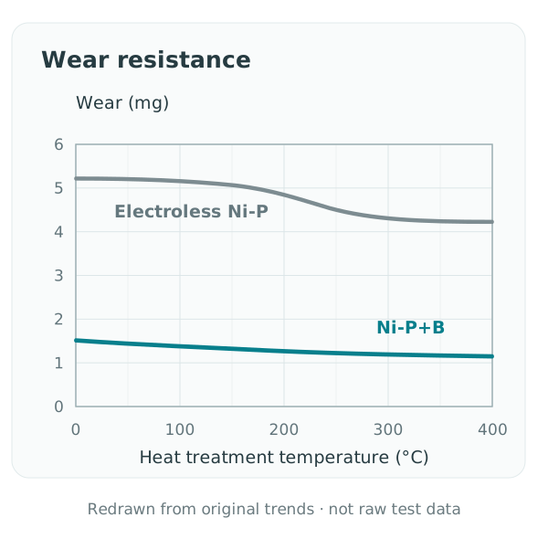
Axes and curves redrawn from the technical data chart, keeping only the charted trend; not original test data and not an acceptance curve for the Ni-P-B process. Workpiece verification should separately agree on test standard, heat treatment conditions and hardness test force.
Check the original reference chart ↗02 / APPLICATIONS
Select by the failure problems of contact surfaces.
First confirm the part's wear, impact and dimensional needs, then decide thickness and inspection method.
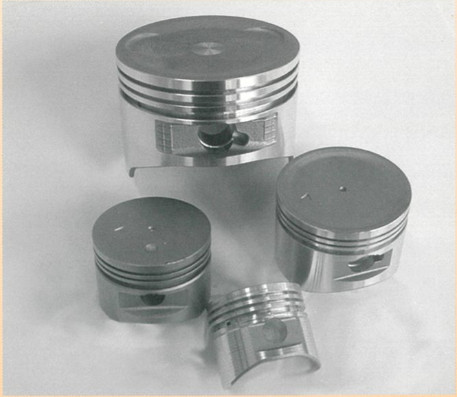 Click to enlarge ⤢
Japanese Ni-P-B data · printed p.10
- Sliding parts
- Sliding contact surfaces requiring hardness and dimensional uniformity; key points to confirm are friction pair, contact pressure, lubrication state and surface roughness.
- Automotive parts
- The Japanese Ni-P-B data lists applications such as pistons, piston rods, gears, valves and camshafts. Actual selection still requires confirming load, temperature and substrate limits.
- Office & electrical components
- For sliding areas and functional surfaces; if soldering or conductivity is required, verification items are agreed separately.
03 / BATH & PROCESS
Ni-P-B process · operating parameters
The following are bath operating conditions for chemical selection and production evaluation.
- Operating temperature
- 81–83 ℃
- pH
- 6.20 ± 0.10
- Deposition rate
- 19 ± 2 μm/h · fresh bath, 82 ℃
- Bath load ratio
- 10–20 mL/cm²
See bath composition & parameter notes
| Item | Parameters & conditions |
|---|---|
| Nickel sulfate | NiSO₄·6H₂O:25 ± 1.0 g/L |
| Coating composition | Low-P, low-B nickel-based alloy; specific composition acceptance ranges are agreed per the corresponding product technical documents. |
| Uniformity | The data gives a qualitative description. Thickness targets, key measurement points and dimensional tolerances must be confirmed per workpiece. |
| Heat treatment | The ≥700 HV on this page is an as-deposited reference value and does not represent hardness after heat treatment; whether and how to heat-treat is confirmed per the part's use. |
Source: operating conditions on p.4 of the Ni-P-B process technical data. Deposition rate is a reference under initial conditions and cannot be equated directly with production takt over the whole bath life.
04 / TECHNICAL IMAGES
Zoom in on images and application parts.
View the shapes and contact areas of application parts; click images to enlarge.
Click to enlarge ⤢Uses the original scanned photo from the Japanese Ni-P-B data, printed p.10.
Enlarge ↗Application needs & evaluation cases
View candidate coatings, related Q&A and verification checklists in the context of specific part failure problems.
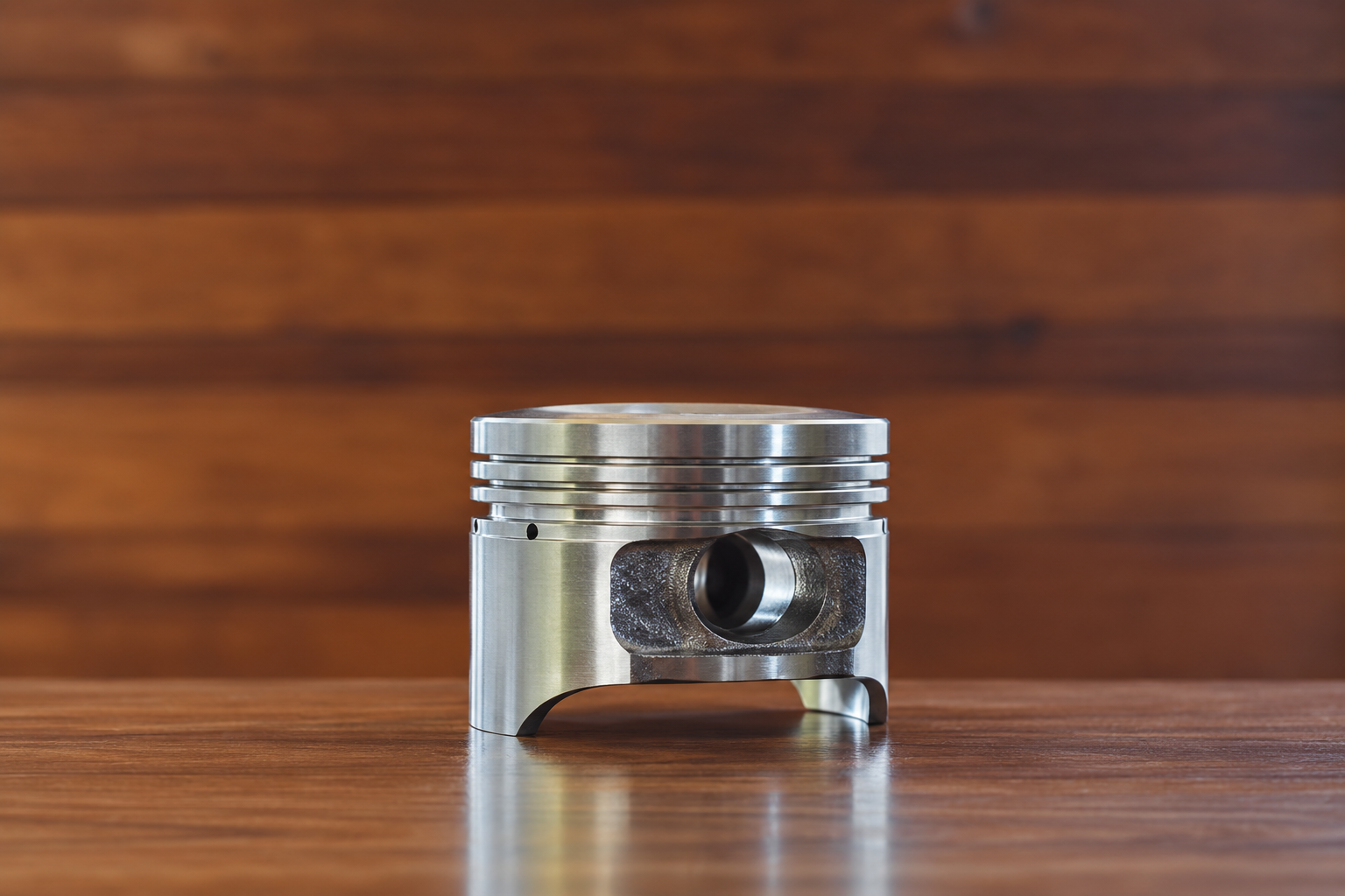
The original coating was discontinued and the aluminum part has strict dimensional requirements; alternatives are compared around sliding wear.
View details ↗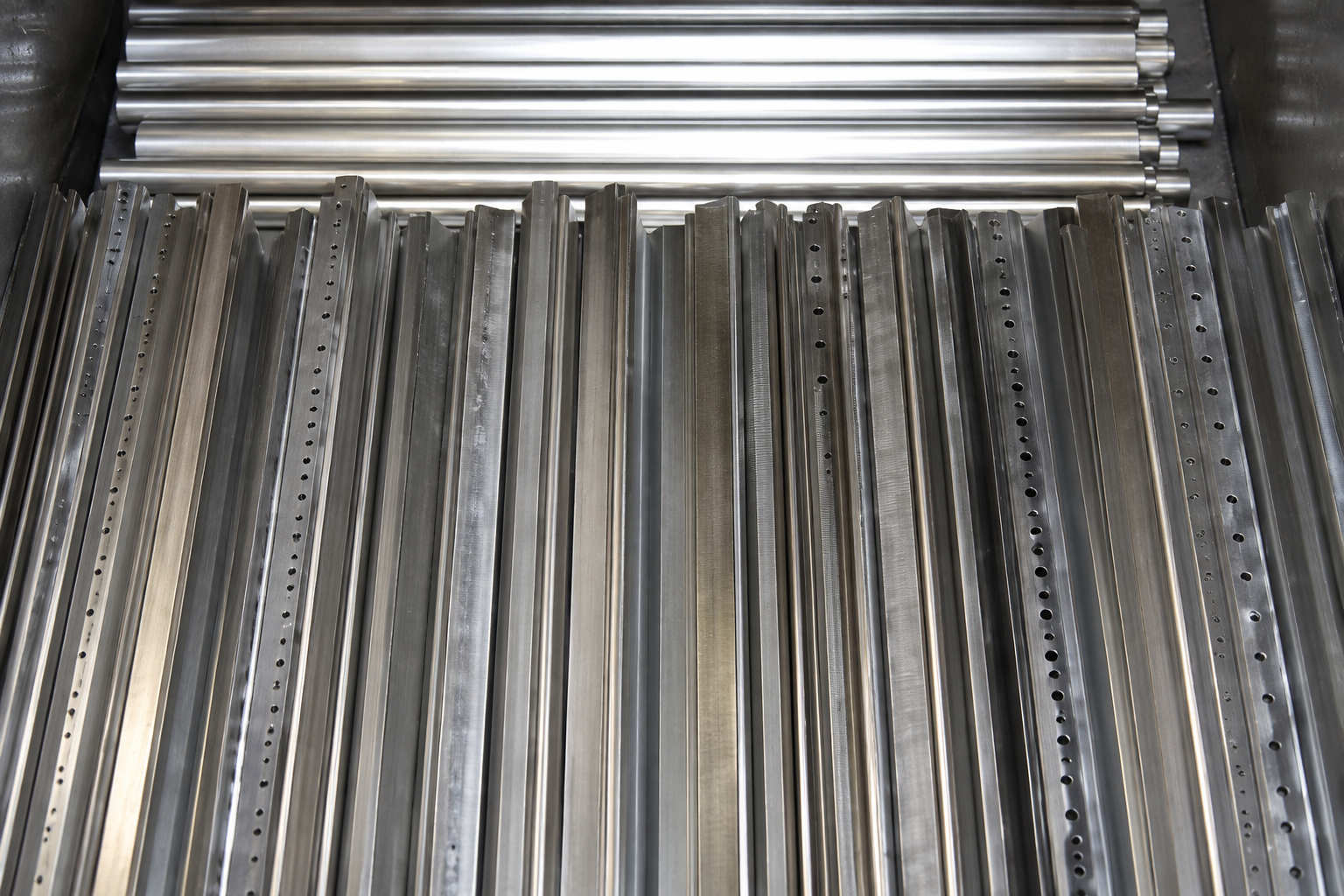
A general electroless nickel 10 μm solution still showed galling; contact conditions after high surface pressure and repeated sliding are compared.
View details ↗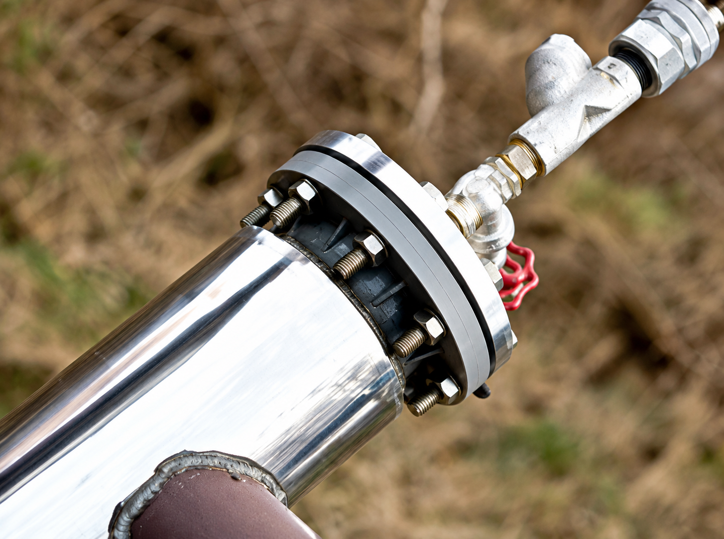
The inner wall of a φ3 × 15 mm through-hole contacts metal wire; comparison carried out with the customer's target of about 2× durability.
View details ↗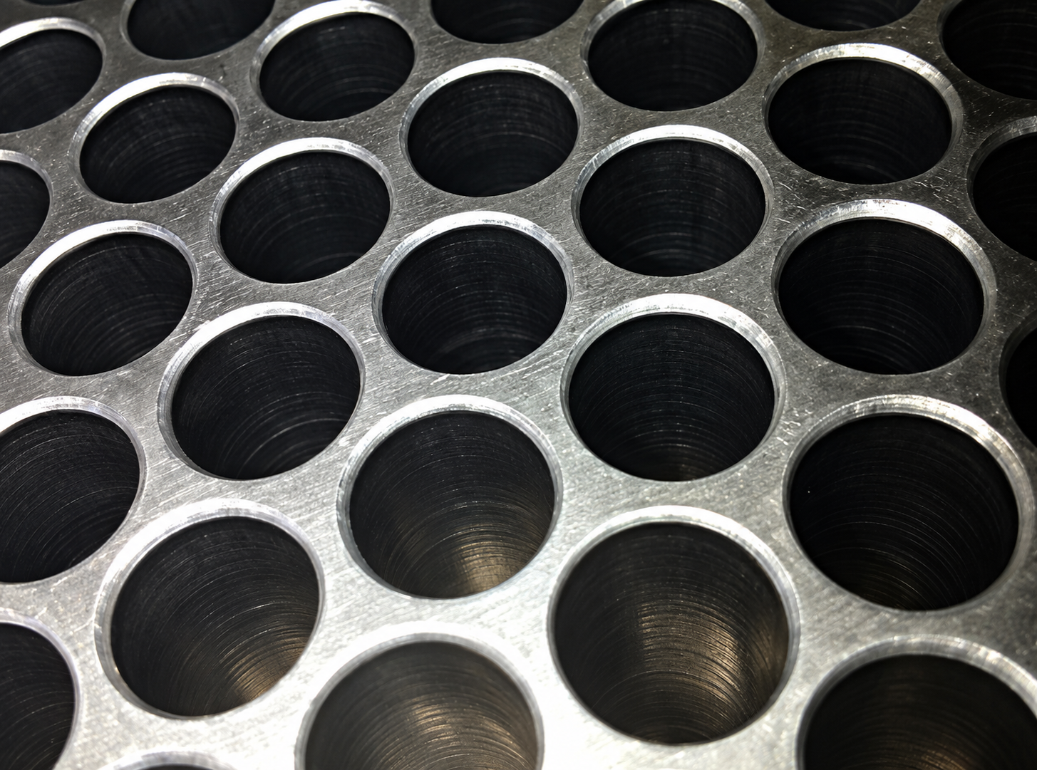
Service environment of about 300 ℃, SUS420J2 substrate; mold life evaluated with resin flow wear.
View details ↗Tell us the service conditions and let's confirm the coating together.
For processing evaluation, please provide substrate, key dimensions, friction pair and service environment; for chemical selection, please add tank size, current process and production takt.
Source: "Ni-P-B process" technical data, pp.2 and 4; company product data ↗; application photos and examples refer to Japanese Ni-P-B data (printed p.10). Updated 2026-09-20.
Performance is reference data; the specific process, substrate, thickness and test conditions together determine final performance, and acceptance requirements are confirmed per part.