AUTRA / PTFE COMPOSITE PLATING
Electroless Nickel-PTFENi-P / PTFE composite coating
Smoother, less sticky precision surfaces. PTFE particles are co-deposited in an electroless nickel coating for sliding fits and mold release needs.
Data reference range corresponding to a PTFE volume fraction of 30–35 vol%, not a guarantee for any workpiece. Friction coefficient is affected by counterpart, load, speed and lubrication state; verify by the corresponding content group and actual conditions—conditions from different groups cannot be applied to one another.
Low-friction surfaces for precision motion and mold release
A Ni-P matrix and PTFE particles form a composite coating. When selecting, check friction, wear and adhesion together with the part's shape and surface requirements.
Sliding fits
For piston rods, guide shafts, pneumatic valves and similar parts; evaluate counterpart, lubrication state and allowable wear.
Mold release & non-stick
For resin molds and forming tools; confirm the effect with contact material, temperature and cleaning method.
Select by workpiece
Provide substrate, dimensions, working surfaces and pretreatment restrictions; an engineer will evaluate the coating and verification method.
See the friction coefficient ranges below by PTFE volume fraction. Friction coefficient is dimensionless; actual behavior is also affected by counterpart material, load, speed and lubrication state.
Test charts & test conditions
See comparisons of oil lubrication, contact angle and surface condition for PTFE composite coatings, plus historical references for content and heat treatment. Test conditions for each group are listed under the charts.
SRV oil lubrication: friction coefficient & wear depth
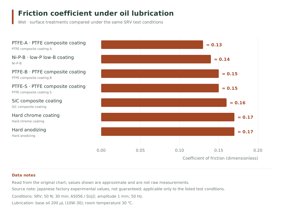
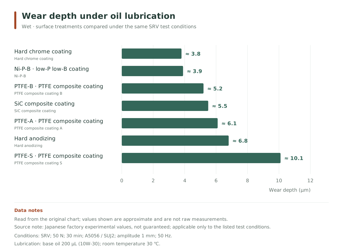
Test method & conditions
- Test equipment
- SRV
- Test equipment
- SRV
- Load / frequency
- 50 N / 50 Hz
- Time / amplitude
- 30 min / 1 mm
- Coated substrate / counterpart
- A5056 / SUJ2
- Lubricant
- 10W-30 base oil, 200 μL
- Temperature
- Room temperature 30 ℃
Japanese factory test values, not guaranteed values. Bar lengths are read from the original charts and values are approximate; they apply only to the listed test conditions.
PTFE composite coating vs. PTFE coating: 2 μL contact angle comparison
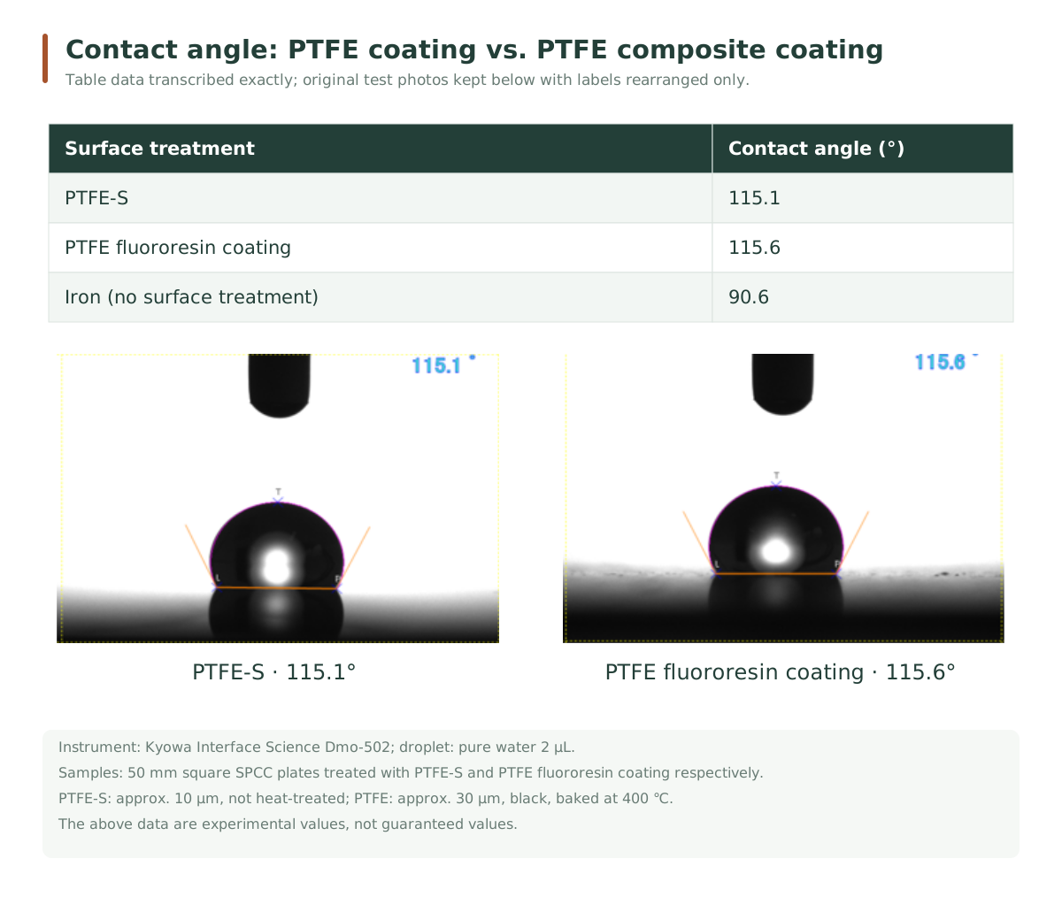
Test method & conditions
- Test instrument
- Kyowa Interface Science Dmo-502 (as labeled in source)
- Droplet
- Pure water 2 μL
- Substrate
- 50 × 50 mm SPCC plate; untreated iron plate as control
- PTFE-S composite coating
- approx. 10 μm; not heat-treated
- PTFE fluororesin coating
- approx. 30 μm; black; baked at 400 ℃
Japanese factory test values, not guaranteed values. PTFE-S is the source's S-series composite coating; this group and the existing 1 μL, 300 ℃, 10 s contact angle test are kept separately.
Surface roughness before and after plating
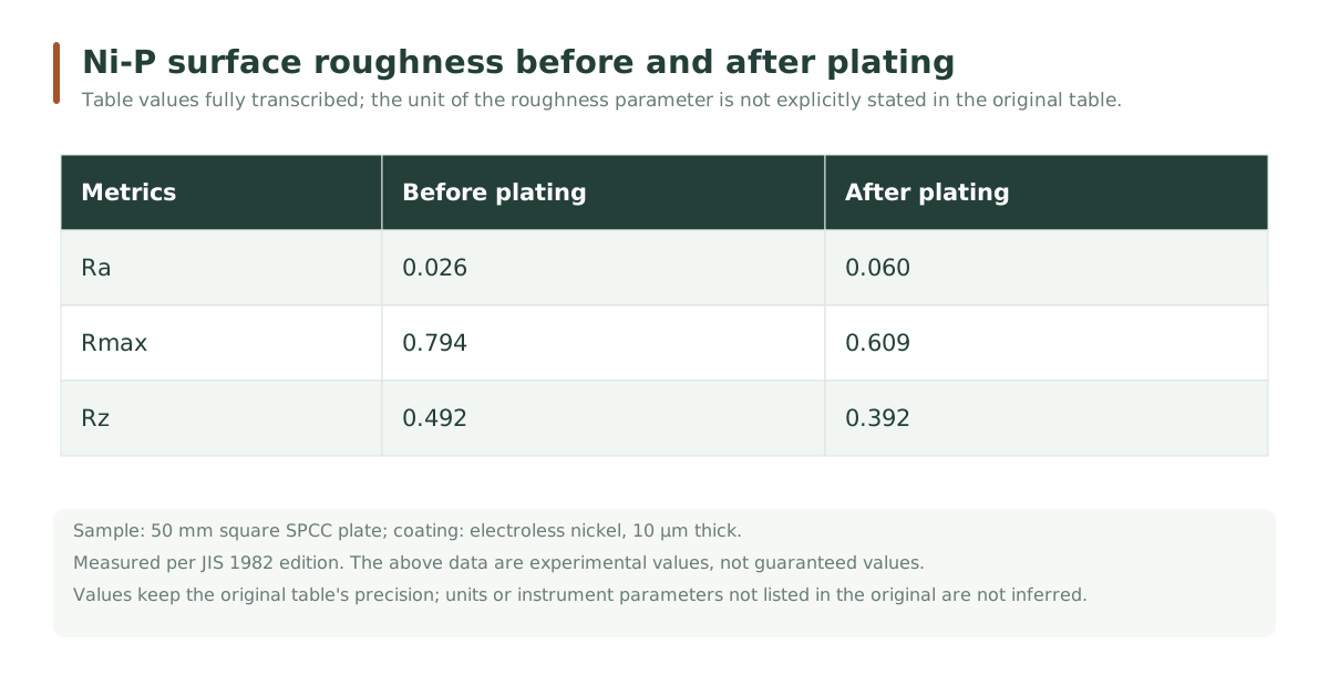
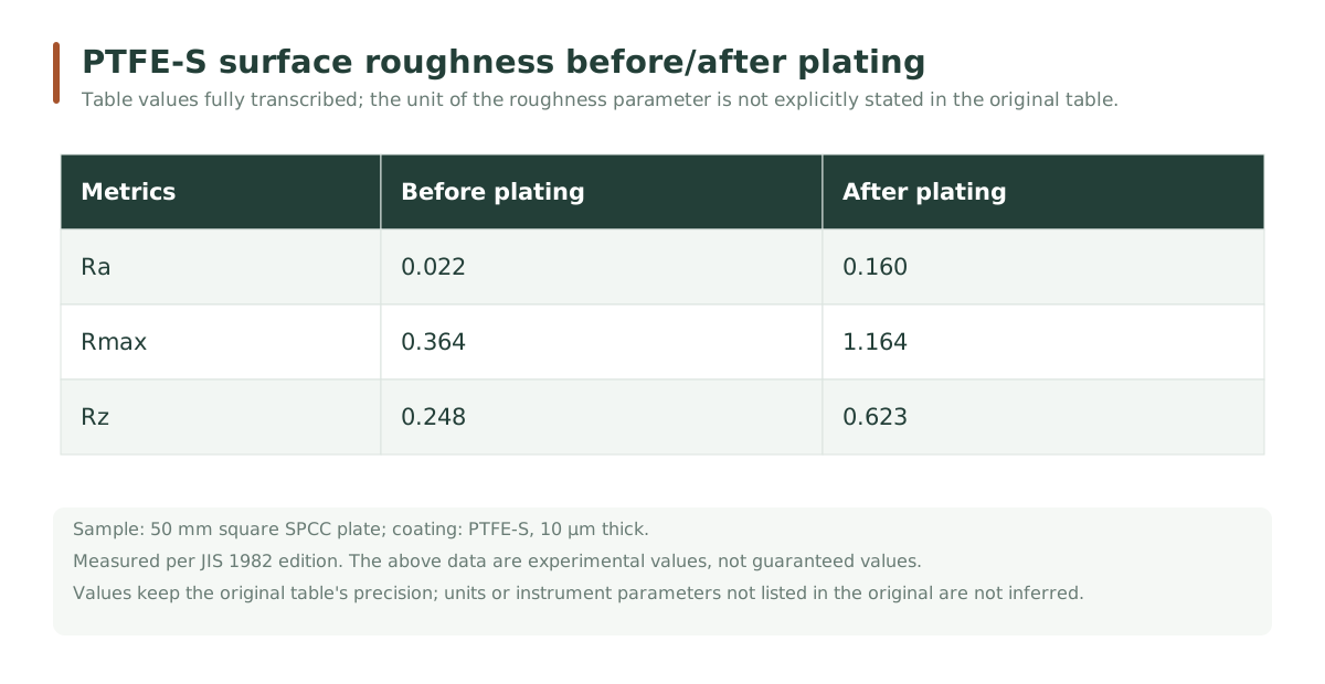
Test method & conditions
- Substrate
- 50 × 50 mm SPCC plate
- Coating / thickness
- General electroless nickel Ni-P / PTFE-S composite coating; both 10 μm
Japanese factory test values, not guaranteed values. Table values are transcribed exactly; missing units are kept as in the original table. PTFE-S refers to the source's S-series composite coating.
PTFE content & performance orientation
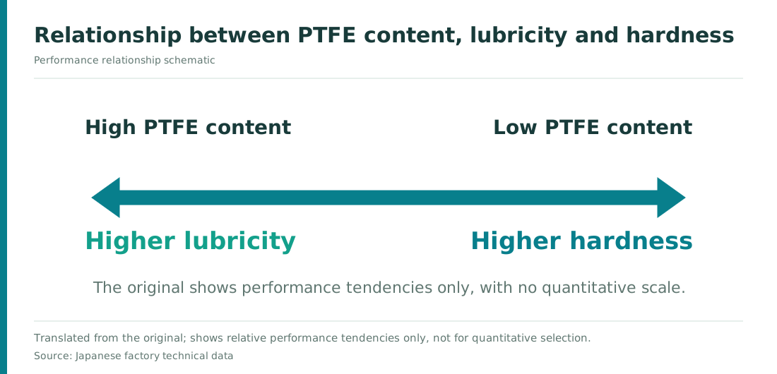
Test method & conditions
- Nature of data
- Qualitative relationship diagram, no numerical scale
The chart expresses the directional relationship between content and performance to explain selection thinking.
PTFE composite coating: hardness reference after 200 ℃ and 300 ℃ heat treatment
| PTFE-B | PTFE-A | PTFE-S | |
|---|---|---|---|
| Post-plating heat treatment 200℃ | 400~550Hv | 250~350Hv | 200~300Hv |
| Post-plating heat treatment 300℃ | 750Hv or above | 400~600Hv | 300~400Hv |
Test method & conditions
- Specimen series
- Source PTFE-B / A / S series
- State
- Post-plating heat treatment 200 ℃ / 300 ℃, listed separately
This table is a Japanese factory specimen reference, not guaranteed values, and cannot be used directly as acceptance criteria for the products on this page. The B series is recorded as ≥750 HV at 300 ℃; this value only indicates the lower limit in that data.
Detailed technical parameters & applicable conditions
On mobile, swipe left and right to see the full table.
| Item | Notes |
|---|---|
| Self-lubricating | PTFE particles distributed on the surface and inside the coating help improve sliding behavior. |
| Non-stick & hydrophobic | For discussing mold release, droplet adhesion and cleaning needs; effects must be verified with actual contact substances and conditions. |
| Conductivity & heat transfer | The metal matrix differs from pure PTFE coatings in electrical and thermal behavior; please provide specific contact resistance, static or thermal conductivity requirements. |
| Corrosion resistance & adhesion | Affected by substrate, pretreatment, coating thickness and porosity; "uniform coverage" should not be understood to mean every workpiece is necessarily pinhole-free. |
Look at the item first, then check the corresponding values and heat treatment conditions. Loads, times and standards for each group correspond to specific tests; formal specifications are confirmed per process and workpiece.
PTFE composite coating · content & performance
PTFE composite coating: comparison by PTFE content
Higher-PTFE series focus on lubrication; lower-content series have higher as-plated hardness.
On mobile, swipe left and right to see the full table.
| Item | 30–35 vol% | 20–25 vol% | 10–15 vol% | 3–7 vol% |
|---|---|---|---|---|
| PTFE volume fraction (vol%) | 30–35 | 20–25 | 10–15 | 3–7 |
| Friction coefficient μ (dimensionless) | 0.05–0.08 | 0.08–0.10 | 0.10–0.15 | 0.12–0.20 |
| As-deposited hardness (HV) | 200–250 | 250–350 | 350–400 | 400–500 |
| Hardness after 300 ℃ heat treatment (HV) | 300–350 | 400–500 | 650–700 | 750–800 |
| Deposition rate (μm/h) | 8.5–10 | 9–11 | 9–11.5 | 9–11.5 |
The recorded friction tests used a HEIDON-14D, load 200 g, φ10 mm alumina ball. Values are selection references under the corresponding data conditions; friction, hardness and deposition rate are different tests, and formal processes should agree test and operating conditions separately.
Friction coefficients are updated to the ranges confirmed by AUTRA, with specific test conditions per the corresponding process documents; other parameters refer to p.1 of the "PTFE composite coating technical data". Performance and heat treatment conditions for different content groups correspond separately and are not a uniform guarantee for any workpiece.
Part applications & selection focus
On mobile, swipe left and right to see the full table.
| Application direction | Typical parts or uses | Conditions to confirm |
|---|---|---|
| Sliding fits | Plungers, piston rods, guide shafts, valves | Counterpart, lubrication method and allowable wear |
| Mold release & cleaning | Resin molds, hoppers, forming tools | Contact material, temperature, release force and cleaning method |
| Precision assemblies | Differential gear washers, semiconductor equipment parts | Clearance, particle requirements and surface condition |
Uses are compiled from technical data and application directions and do not mean every workpiece is suitable. After identifying the key failure problem, agree on the coating and verification method.
Images & technical documents
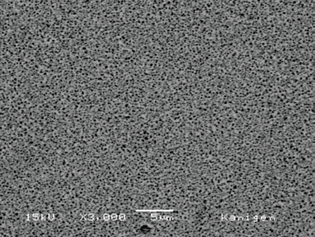
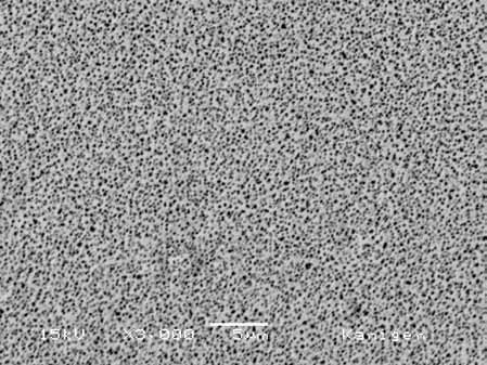
The four SEM images below are arranged by the PTFE content groups above, extracted directly from the original images embedded in the technical data PDF, each keeping its own scale bar.
PTFE volume fraction 30–35 vol% · original SEM from Japanese data
 Click to enlarge ⤢
PTFE volume fraction 20–25 vol% · original SEM from Japanese data
 Click to enlarge ⤢
PTFE volume fraction 10–15 vol% · original SEM from Japanese data
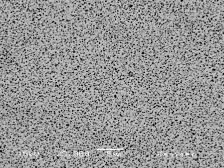 Click to enlarge ⤢
PTFE volume fraction 3–7 vol% · original SEM from Japanese data
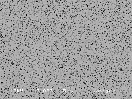 Click to enlarge ⤢
Related performance & test data
Limits of applicability
Public data is a reference for the product system and coating performance; please request the corresponding technical documents to confirm specific chemical processes, bath conditions, thickness and acceptance requirements.
Selection notes
Plating service customers only need to provide targets, substrate and quantity; an engineer will determine the coating. Chemical customers should also provide tank size, current process, operating temperature and production takt to confirm the specific process TDS.
Source: company technical data ↗; Japanese series data and micrographs: "PTFE composite coating technical data" · Updated: 2026-09-30
Application needs & evaluation cases
View candidate coatings, related Q&A and verification checklists in the context of specific part failure problems.
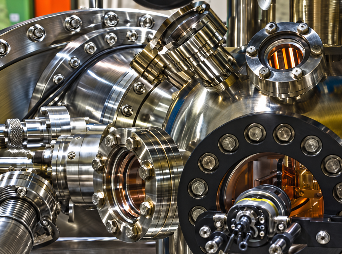
Halogen gas corrosion and foreign matter adhesion occur in vacuum; corrosion resistance and sliding behavior are checked separately.
View details ↗
Existing electroplated nickel bolts galled and seized; focus on fastening, disassembly after use and thread fit.
View details ↗