Black nickel surface treatment
BLACK NICKEL · ELECTROLESS PLATINGTWO PROCESSES / BLACK FINISH
Black nickel
Deep black appearance, two process options.
The post-plating blackening type combines a deep black appearance with continuous production control; the direct black type absorbs ultraviolet, visible and near-infrared light through a fine textured structure for low-reflection optical applications. Choose the right black nickel solution based on part geometry and production method.
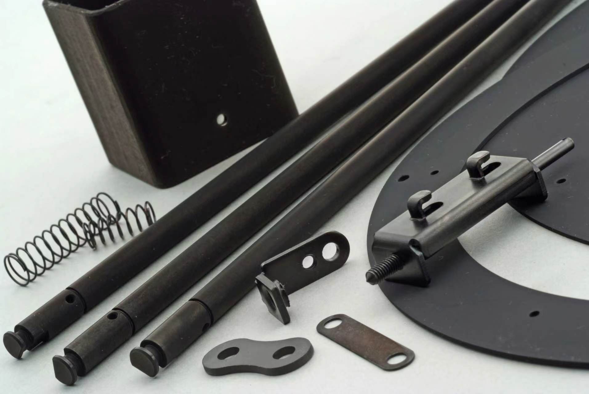
01 / PRODUCT & FINISH
From real samples, understand the texture of black nickel.
First look at the appearance, then the process. Videos and images show the results of each process so you can observe part surfaces and details.
Post-plating blackening type
Uniform deep black, suited to continuous production control.
A lead-free Ni-P electroless system that achieves a uniform, deep black appearance through pre-dip and subsequent blackening. The bath can be continuously managed through analysis and replenishment, suiting production that requires continuous bath use.
- Separate blackening step: the black appearance is produced after electroless plating.
- Analysis & replenishment: the plating bath and blackening solution are each managed to their own standards.
- Underlayer: a Ni-P underplate improves overall corrosion resistance.
- Electroless plating temperature
- 86–93℃
- Electroless bath pH
- 5.6± 0.1
- Subsequent blackening time
- 1.5–5min
Blackening temperature is 20–30℃; 1.5–5 minutes refers only to the blackening step, not the time of the whole nickel plating process.
See the process flow
Direct-black type
Black as deposited, combining light absorption and low reflection.
This process uses a lead-free alkaline electroless bath; the coating itself turns black as it deposits. The uniform coverage of electroless plating suits complex part geometries; applications include optical uses such as cameras, microscopes and precision analytical instruments.
- Black as deposited: the black appearance forms as the electroless coating deposits.
- Broadband absorption: absorption covers ultraviolet, visible and near-infrared.
- Uniform coverage: inner and outer surfaces of complex shapes can be treated.
- Electroless plating temperature
- 87–93℃
- Recommended treatment time
- 40–60min
- Recommended coating thickness
- 5–10μm
According to laboratory data, the low-reflection effect is affected by thickness, wavelength and treatment conditions and should be confirmed against actual optical requirements.
See absorption data & NASA applicationImages and videos show appearance. Lighting, viewing angle and screen affect color rendering; final appearance is confirmed on actual samples under the same conditions.
02 / LIGHT ABSORPTION & APPLICATIONS
Direct black type, turning black into a light-absorbing surface.
According to laboratory data, the direct black type combines broadband light absorption and low reflection. Learn about this functional coating through spectral curves, thickness variation and material properties.
BROAD-SPECTRUM ABSORPTION
Covering ultraviolet, visible and near-infrared.
According to laboratory data, the coating's fine textured surface and columnar structure help absorb incident light and reduce surface reflection, suitable for optical parts sensitive to stray light.
- UVUltraviolet
- VISIBLEVisible light
- NEAR IRNear-infrared
Based on laboratory data. Specific reflection varies with wavelength, thickness and surface condition.
Fine particles and columnar structure
The surface shows clustered texture with micro-particles of about 0.2–0.4 μm. Grooves between particles and the porous structure together form a light-absorbing surface.
Thicker coating, lower gloss and reflection
As the coating grows, the micro-grooves deepen further. Laboratory data at different incidence angles all show gloss decreasing as thickness increases.
For complex shapes and precision parts
Deposits uniformly on inner and outer surfaces and sharp corners of complex parts, suitable for parts where thickness uniformity and dimensional accuracy matter.
LABORATORY DATA / Optical & material data
See surface performance through curves.
Based on laboratory data, showing spectral reflectance, the thickness–gloss relationship and hardness change with heat treatment. Curve and table values are approximate readings from the charts.
Wavelength vs. reflectance
Horizontal axis: wavelength (nm) · vertical axis: reflectance (%)
Enlarge ↗
The short-wavelength curve lies close to the zero baseline; the table uses "<0.1%" for the approximate low value read from the chart, not an absolute zero reflectance. The curve is only for observing the trend of the sample shown; actual parts should be tested per the agreed target band, measurement angle and thickness and cannot use this directly as an acceptance curve.
Spectral reflectance reference
The following are approximate readings from the curve shown, only for understanding the relationship between wavelength and reflection, not guaranteed values for workpieces.
| Wavelength nm | Reflectance approx. curve value |
|---|---|
| 200 | <0.1% |
| 500 | <0.1% |
| 1000 | <0.1% |
| 1500 | <0.1% |
| 2000 | approx. 0.26% |
| 2500 | approx. 1.05% |
| 2700 | approx. 1.80% |
Thicker coating, lower gloss
Horizontal axis: thickness (μm) · vertical axis: gloss (%)
Enlarge ↗
The chart distinguishes 45°, 60° and 75° incidence angles. Gloss describes the appearance response at a specified angle and is listed separately from spectral reflectance and absorptance.
| Thickness μm | 45° | 60° | 75° |
|---|---|---|---|
| 2 | <0.5 | approx. 7.0 | approx. 32 |
| 4 | <0.5 | approx. 1.6 | approx. 15 |
| 6 | <0.5 | approx. 1.1 | approx. 9 |
| 10 | <0.5 | approx. 0.5 | approx. 2 |
Heat-treatment temperature vs. Vickers hardness
Horizontal axis: heat treatment temperature (℃) · vertical axis: Vickers hardness (HV)
Enlarge ↗
According to laboratory data, as-plated hardness is about 220–280 HV; it rises with heat treatment temperature, reaches the charted peak around 500℃, then declines. The curve illustrates the sample's trend.
Performance test samples were prepared at 90℃, pH 8.5. The heat treatment curve and current production bath parameters are listed separately; specific processes must be verified on the workpiece.
View conductivity, phase transition temperature, magnetism and surface area data
| Item | State / stage | Value |
|---|---|---|
| Conductivity | As-plated | 0.06% IACS |
| Conductivity | After 300℃ heat treatment | 0.3% IACS |
| Melting temperature | Start / end | 884 / 901℃ |
| Solidification temperature | Start / end | 864 / 853℃ |
| Item | State / condition | Value |
|---|---|---|
| Mass magnetic moment | As-plated, 5 kOe | 1.29 emu/g |
| Mass magnetic moment | Annealed at 200℃, 5 kOe | 1.5 emu/g |
| Mass magnetic moment | Annealed at 300℃, 5 kOe | 4.9 emu/g |
| Projected area | Average | 9.2×10² μm² |
| 3D surface area | Average | 8.4×10⁴ μm² |
Based on laboratory data. Solidification occurs during cooling, so the start temperature is higher than the end temperature; phase transition temperatures do not represent service temperatures. The surface area ratio is about 91×, summarized as about 100×, describing the micro-morphology.
APPLICATION / Aerospace application
NASA satellite application
Used to suppress laser reflection.
This black electroless coating has been used on NASA space satellites to suppress laser reflection.
Historical application example. Thickness, wavelength band and service conditions for specific parts must be confirmed separately.
Cameras, microscopes & analytical instruments
Used in optical devices and analytical instrument components, meeting the needs of precision measurement and thickness uniformity.
UV suppression inside equipment
This coating is used on parts of semiconductor manufacturing equipment that require ultraviolet suppression.
CPU / LSI thermal radiation & heat dissipation
The abundant micro-texture and columnar structure increase surface area, providing conditions for thermal radiation and heat dissipation applications.
LABORATORY COATING PROPERTIES
Beyond light absorption, multiple surface properties.
Based on laboratory data, the following are sample observations and test results. Performance test samples were prepared at 90℃, pH 8.5; see the comparison table below for current process operating parameters.
Hardness
220–280 HV
According to laboratory data, as-plated Vickers hardness is about 220–280 HV. Hardness increases after heat treatment, with the charted peak around 500℃.
Laboratory data · as-plated & heat-treatedColor stability after heat treatment
400℃ × 1 hour
Samples showed almost no discoloration after heat treatment at 400℃ × 1 hour in an air furnace. This is an appearance record under the specified heat treatment and does not represent a long-term service temperature.
Laboratory data · heat treatment appearance recordAdhesion
No peeling in bend test
After heating at 200℃, samples were bend-tested and no coating peeling was observed.
Laboratory data · bend testCorrosion performance with underplate
14 -day damp heat test
Ni-P underlayer 2–5 μm, black layer 5, 10 and 15 μm respectively; after 14 days at 35℃ and 90% RH, no rust was observed on any sample. This is a damp heat test.
Laboratory data · samples with underplateMicroscopic surface area
approx. 100 ×
According to laboratory laser microscope measurement, the actual surface area is about 100× the projected area. This value describes surface morphology and does not represent a multiple of heat dissipation efficiency.
Laboratory data · 3D morphologyConductive, dust-resistant & lubricious
Functional metal surface
The coating itself is conductive. Conductivity helps resist dust; the micro-texture reduces contact area with the counterpart, aiding lubrication.
Laboratory data · material propertiesBased on laboratory data, the above properties illustrate the direct black coating's characteristics; actual parts must be confirmed according to substrate, thickness, target wavelength band and service environment.
Test charts & test conditions
Compare emissivity and gloss for different black treatments. The black electroless coating in the gloss chart is the direct black type; test methods and known standards for each group are listed under the charts. Click a chart to enlarge.
Total emissivity calculated from room-temperature reflectance spectra
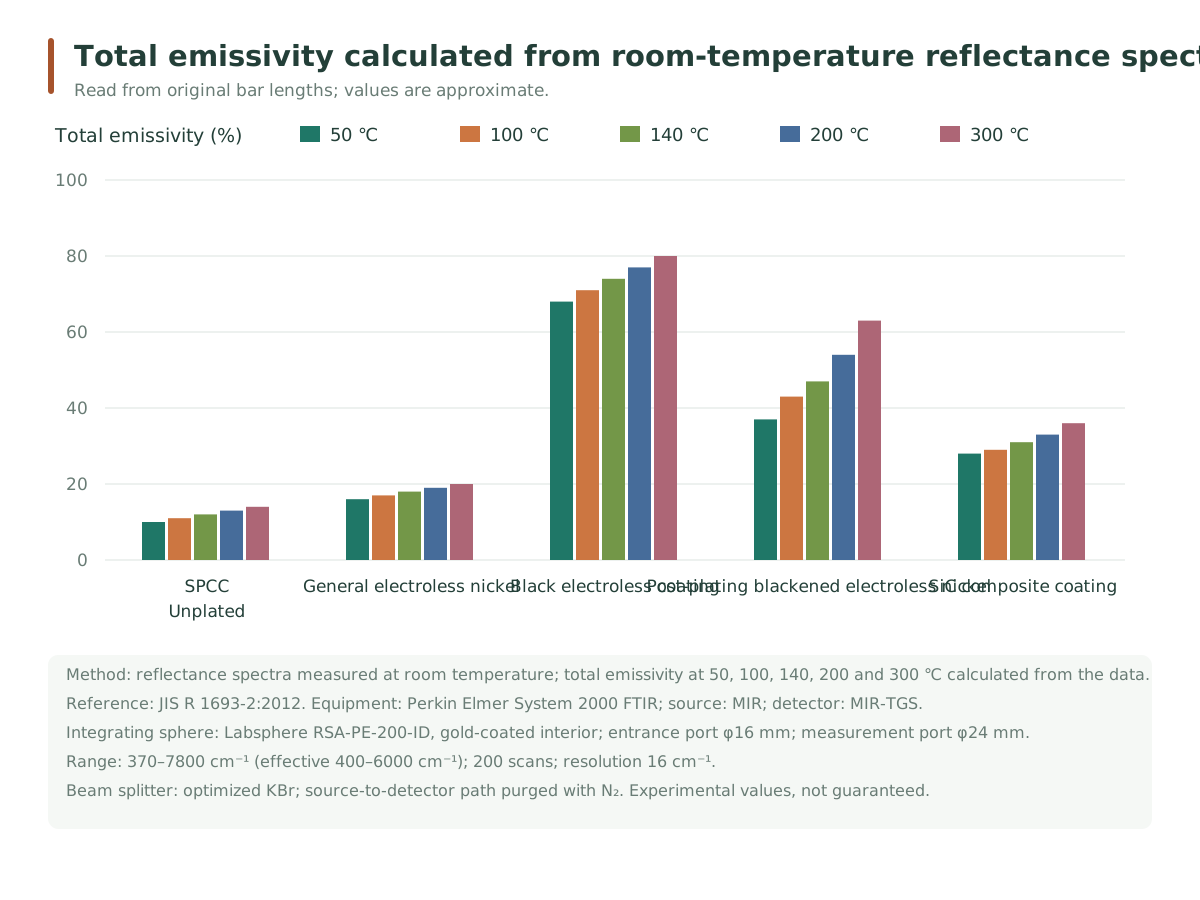
Test method & conditions
- Standard cited by source
- JIS R 1693-2:2012
- Measurement & calculation method
- Reflectance spectra measured at room temperature, then total emissivity calculated for 50 / 100 / 140 / 200 / 300 ℃
- FTIR / light source / detector
- Perkin Elmer System 2000 / MIR / MIR-TGS
- Integrating sphere
- Labsphere RSA-PE-200-ID; gold-plated inner wall
- Entrance port / measurement port
- φ16 mm / φ24 mm
- Wavenumber range
- 370–7800 cm⁻¹; effective range 400–6000 cm⁻¹
- Scans / resolution
- 200 scans / 16 cm⁻¹
- Beam splitter / optical path
- optimized KBr / N₂ purge
- Coating thickness / substrate details
- Not fully provided by the source beyond the material labels in the chart
Japanese factory test values, not guaranteed values. Bar lengths are estimated from the original chart; this is total emissivity at specified temperatures calculated from room-temperature spectra. Black electroless coating and post-blackened electroless nickel are two different processes.
Gloss of black electroless coating vs. other black treatments
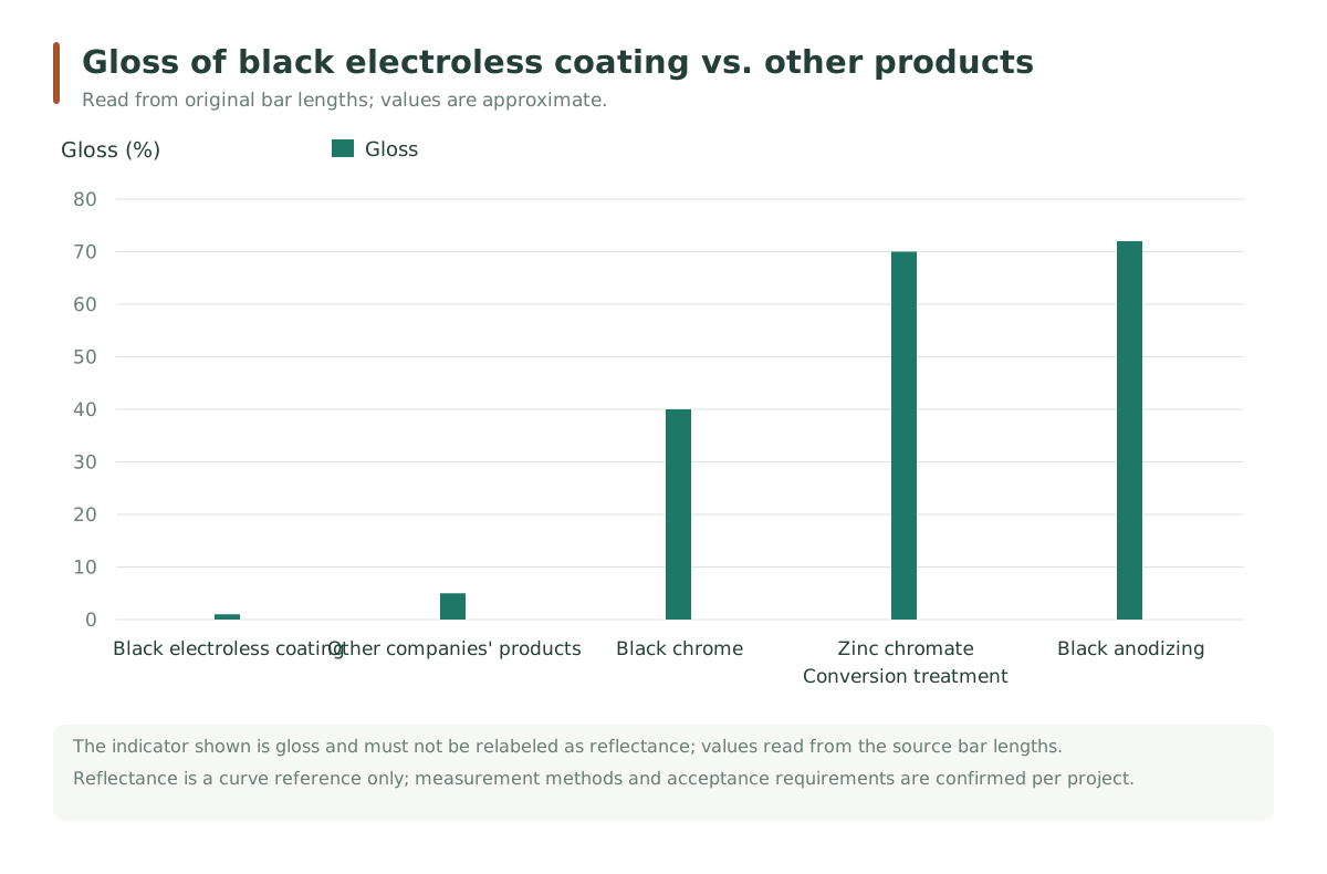
Test method & conditions
- Metrics
- Gloss (unit shown in source chart is %)
Japanese factory test values, not guaranteed values. Bar lengths are estimated from the original chart. The metric shown is gloss, presented separately from reflectance and total emissivity on this page.
03 / PROCESS COMPARISON
Both black nickel, each process with its own focus.
The two options differ in how black is formed, pH and bath management. Below are reference process conditions for both, for selection comparison.
Swipe the table left and right to see full parameters for both options →
| Comparison item | Post-plating blackening type | Direct-black type |
|---|---|---|
| Black formation | After electroless plating, blackened in a separate treatment | Turns black directly during electroless deposition |
| Bath management | Analysis and replenishment, continuous-use type | Single-use solution |
| Electroless plating temperature | 86–93℃ | 87–93℃ |
| Electroless bath pH | 5.6 ± 0.1 | 8.20 ± 0.10 |
| Nickel sulfate hexahydrate concentration | 22.5 ± 2 g/L | 25 ± 1 g/L |
| Time & thickness | Blackening: 1.5–5 minutes, 20–30℃This temperature and time apply only to the subsequent blackening step and are not used to infer the preceding nickel plating time or thickness. | Recommended nickel plating: 40–60 minutesCorresponds to the recommended thickness of 5–10 μm; plate for 30 minutes or more to form a good black. At bath make-up, the reference plating rate at 90℃ is 8 ± 2 μm/h. |
| Agitation | Air agitation, mechanical agitation or workpiece rocking | Propeller or circulation agitation, optionally with workpiece rockingAir agitation is prohibited; excessive flow may affect color uniformity. |
| Corrosion design | Ni-P underplate recommended | Thin Ni-P underplate recommended |
| Selection focus | Uniform deep black appearance; analysis/replenishment and continuous production control | Direct black; uniform coverage of complex shapes; optical low-reflection uses |
Both options are lead-free. The table lists each process's own conditions and cannot be used as a performance ranking under identical conditions; the specific process should be determined with the substrate, pretreatment, underplate and sample verification.
04 / PROCESS SELECTION
Select by appearance target and production method.
Clarify substrate, part geometry, target blackness and any low-reflection or corrosion requirements, then determine the process route and verification conditions.
Need a deep black appearance
with continuous bath management.
Electroless plating and blackening are managed separately, with the bath maintained by analysis and replenishment. The reference flow for general ferrous materials can serve as a starting point for discussion.
- 01 Substrate pretreatment & Ni-P underplate
- 02 Dedicated Ni-P electroless plating
- 03 Pre-dip → blackening
- 04 Neutralizing, drying & required post-treatment
Need uniform black coverage
with attention to optical reflection.
For black low-reflection needs on parts for cameras, microscopes, precision analytical instruments and similar. Batches and loading are arranged around the single-use bath.
- 01 Determine pretreatment by substrate
- 02 Thin Ni-P underplate to improve corrosion resistance
- 03 Electroless deposition forms black
- 04 Confirm appearance, thickness and reflection against targets
What else to consider when confirming the process?
Post-plating blackening type: manage nickel plating and blackening separately
Reference pre-dip conditions are room temperature for 30–60 seconds; after pre-dip, go straight into blackening without rinsing. In actual production, rinsing, analysis/replenishment and post-treatment arrangements must be determined with the complete process; the flow above is a selection overview.
Direct black type: balance loading and flow
Reference bath load ratio V/A is 60–100 mL/cm². Excessive flow causes uneven color, and lifting workpieces during nickel plating may cause streaks. Batch conditions should be confirmed with the tank, workpiece area and rocking method.
05 / QUESTIONS & ANSWERS
What you may want to know about black nickel.
What is the main difference between the post-plating blackening type and the direct black type?
The post-plating blackening type obtains a deep black through a separate blackening step after electroless plating; its bath can be analyzed, replenished and used continuously. The direct black type forms black directly during deposition and uses a single-use bath. They differ in pH, agitation and production management conditions, so processes must be set up separately.
Which should I consider for low-reflection applications?
According to laboratory data, the direct black type absorbs ultraviolet, visible and near-infrared light and suits optical low-reflection applications. Its fine texture and columnar structure aid absorption, and increasing thickness lowers gloss and reflection. Specific performance must be verified against the target band and part requirements. The two black nickels use different processes, and their optical parameters cannot be applied interchangeably.
Can absorptance be calculated directly from reflectance?
Absorptance, total reflectance and transmittance satisfy energy conservation. Only when the sample is opaque and reflectance includes all specular and diffuse reflected light can absorptance ≈ 100% − reflectance be used. Therefore absorption should be evaluated from optical measurement records of the corresponding sample; a simple conversion cannot be treated as a measured result.
Does a black coating mean sufficient corrosion resistance?
A black appearance alone does not indicate corrosion resistance. Data for both options recommend improving corrosion resistance with a Ni-P underplate; the porous structure of the direct black type offers limited protection to the substrate by itself. Actual corrosion verification conditions should be set with the substrate, underplate and thickness.
What information helps confirm the treatment plan?
We recommend preparing the substrate material, part drawings or samples, area to be plated, dimensional tolerances, target black sample panel, and corrosion or optical targets. For low-reflection uses, please add the target band and measurement conditions; for mass production, please add batch quantity and existing production line conditions.
Hand your requirements to AUTRA engineers
Provide the substrate, target performance and quantity, or your existing tanks and production conditions, and an engineer will confirm the applicable solution.