Processing customers, start here
Meet conduction, contact or grounding needs
Industry reference: typical resistivity of electroless nickel is about 30–100 μΩ·cm.
Data come from Nickel Institute technical documents and are not an AUTRA processing guarantee. Resistivity varies with coating composition and heat treatment; a workpiece's contact resistance and a material's resistivity are different metrics and must be tested under the actual contact condition.
Tell our engineers your requirements
Enter substrate, quantity and performance targets; if you don't know the specific metrics, you can describe the problem you face.
Detailed test data · expand test conditions, historical data and interpretation
Conclusions first
The following are functional definitions and evaluation directions, not a list of tested parameters for each process.
Performance of the same coating changes with composition, thickness and heat treatment.
Electrical and photothermal metrics require an agreed test method and cannot be inferred from appearance or hardness.
Test conditions
For a specific workpiece evaluation, state the material, operating environment and acceptance requirements; read the test conditions separately for each data group on this page.
Data & interpretation
Mechanical properties
The table scrolls horizontally; the first column keeps the comparison items.
| Property | Meaning & typical scenarios | Candidate options | Corresponding products |
|---|---|---|---|
| Hardness | The surface's resistance to local indentation; wear selection must also consider the wear mechanism | Ni-P, Ni-P-B, SiC composite plating | Ni-P process selection overview ↗ Electroless Ni-P-B plating ↗ SiC composite electroless nickel ↗ |
| Coating thickness uniformity | Consistency of thickness at different locations; for precision fits and complex parts | Electroless nickel; critical dimensions must be confirmed separately | Ni-P process selection overview ↗ |
| Low friction & anti-adhesion | Reduces friction and material transfer at moving interfaces; for sliding fits | PTFE composite electroless plating | Electroless Nickel-PTFE | PTFE composite electroless plating ↗ |
Each row gives a functional meaning and candidate options; it is not a design or contract specification. Please confirm test records for the specific product, substrate and operating conditions.
Electrical properties
The table scrolls horizontally; the first column keeps the comparison items.
| Property | Meaning & typical scenarios | Candidate options | Corresponding products |
|---|---|---|---|
| Contact resistance | Resistance at a conductive contact interface; affected by surface oxidation, pressure, etc. | Candidate coatings such as Ni-B; must be measured | Electroless nickel-boron Ni-B ↗ |
| Solderability | Ability to form a reliable joint with a specified solder; watch storage and surface condition | Ni-P, Ni-B; confirm per soldering process | Ni-P process selection overview ↗ Electroless nickel-boron Ni-B ↗ |
| Magnetism | The coating's response to magnetic fields; related to composition and heat treatment | Ni-P; test metrics must be agreed | Ni-P process selection overview ↗ |
Each row gives a functional meaning and candidate options; it is not a design or contract specification. Please confirm test records for the specific product, substrate and operating conditions.
Chemical properties
The table scrolls horizontally; the first column keeps the comparison items.
| Property | Meaning & typical scenarios | Candidate options | Corresponding products |
|---|---|---|---|
| Resistance to media corrosion | Stability in a specific medium, concentration and temperature | Ni-P; see corrosion resistance data | Ni-P process selection overview ↗ |
| Surface wettability | How far a liquid spreads on the surface; can be compared by contact angle | PTFE composite electroless plating; see water repellency data | Electroless Nickel-PTFE | PTFE composite electroless plating ↗ |
| Non-stick & easy cleaning | Reduces material adhesion, eases mold release and cleaning | PTFE composite electroless plating; must be verified with actual materials | Electroless Nickel-PTFE | PTFE composite electroless plating ↗ |
Each row gives a functional meaning and candidate options; it is not a design or contract specification. Please confirm test records for the specific product, substrate and operating conditions.
Optical & thermal properties
The table scrolls horizontally; the first column keeps the comparison items.
| Property | Meaning & typical scenarios | Candidate options | Corresponding products |
|---|---|---|---|
| Low reflection | Reduces reflected light in specific bands and angles; for optical parts | Post-plating blackening systems; wavelength and measurement geometry must be agreed | |
| Black appearance | Appearance requirements for color, gloss and uniformity; not the same as a low-reflection metric | Black decorative coatings | Black nickel: post-plating blackening & direct black deposition ↗ |
| Heat resistance & heat-treatment compatibility | Retaining function after temperature exposure; also check substrate distortion and coating changes | Ni-P, Ni-P-B; temperature and time must be specified | Ni-P process selection overview ↗ Electroless Ni-P-B plating ↗ |
Each row gives a functional meaning and candidate options; it is not a design or contract specification. Please confirm test records for the specific product, substrate and operating conditions.
Test charts & test conditions
View charts, methods and conditions test by test. Vector charts can be clicked to enlarge; each data group applies only to the corresponding specimens and test conditions.
Surface roughness before and after plating
Test method & conditions
- Source standard as cited
- JIS 1982 edition (as cited by source)
- Substrate
- 50 × 50 mm SPCC plate
- Coating / thickness
- General electroless nickel Ni-P / PTFE-S composite coating; both 10 μm
- Metrics
- Ra、Rmax、Rz
Ra, Rmax and Rz describe surface roughness; comparisons should use the same measuring method and units. PTFE-S refers to the source’s S-series composite coating; the surface requirements of a specific workpiece are agreed per drawing.
Source
Surface roughness before and after brass-brush cleaning
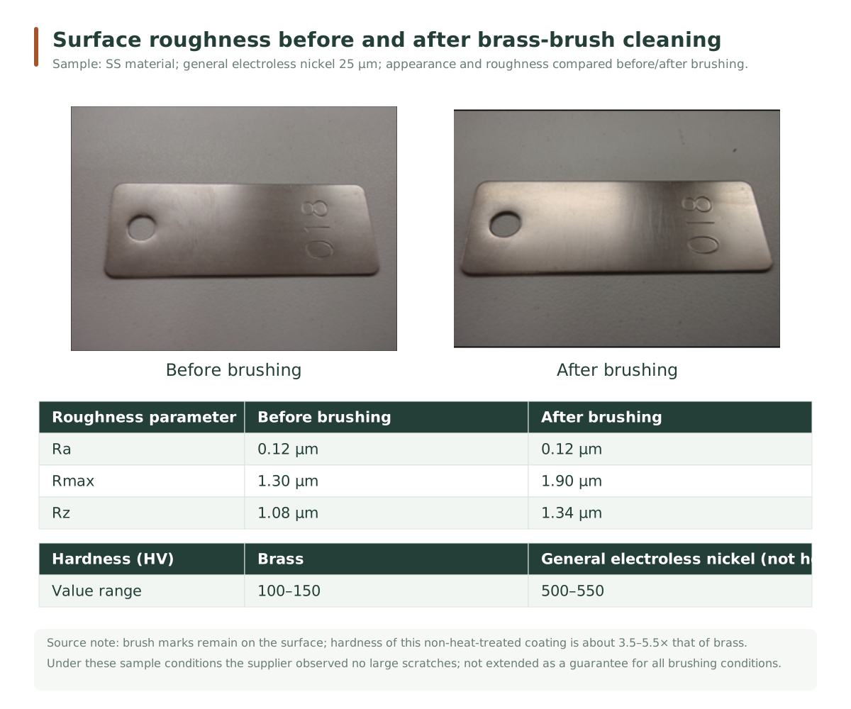
Test method & conditions
- Substrate / coating
- SS material / general electroless nickel 25 μm
- Treatment
- Comparison before and after brass-brush cleaning
- Hardness reference
- Brass 100–150 HV; non-heat-treated electroless nickel 500–550 HV
- Roughness unit
- μm; retained as explicitly stated in this group’s original chart
Japanese factory test values, not guaranteed values. Brush marks are visible in this group; the listed values apply only to the source specimens and cleaning process.
Source
Example of scratch adhesion evaluation
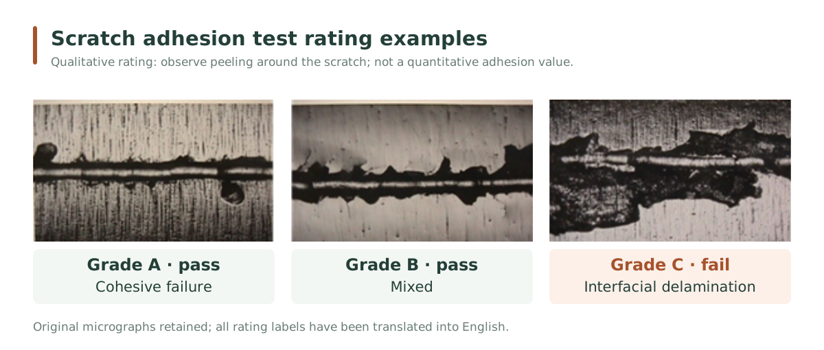
Test method & conditions
- Method
- Diamond stylus scratch; observe surrounding delamination
- Source evaluation
- Grades A and B pass; grade C fails
- Nature of data
- Micrographs and qualitative rating examples
This figure is a qualitative example of judging scratch appearance and does not represent quantitative adhesion; the inspection method and pass criteria for a specific workpiece are agreed per order.
Source
Selection advice & data boundaries
If thermal conductivity, thermal expansion or emissivity are key metrics, please provide the service temperature, dimensions and target values separately, and agree on the test method.
You can continue to the related products to see the material systems, then confirm manufacturability and the test plan through drawing evaluation.
When evaluating, first select the function, measuring method and acceptance range, then describe the corresponding operating conditions.