Surface engineering cases & FAQ
Do you need parts plated, or do you want to buy chemicals? Choose the matching entry to see common questions first.
Plating service FAQ
First confirm the workpiece, goals and quantity, then discuss process, cost and delivery requirements.
Can my part be processed? What if I haven't decided on a coating?
First tell us the material grade, what the part is used for, and the problem you want to solve, such as corrosion, wear, sticking or fit dimensions. If you don't know the coating name yet, you can still talk to us first.
Suitability also depends on material state, surface condition, structure and service environment; for special materials or complex workpieces, a sampling plan can be confirmed first.
What should I prepare for a first inquiry?
Just provide the material, quantity and main performance goals. If known, you can add outer dimensions, key tolerances, service media and temperature, and desired processing time.
Once a specific evaluation starts, add the drawing revision, key working surfaces, no-plating zones, target thickness and acceptance requirements; for uncertain items you can choose "ask an engineer to suggest".
The drawings are confidential—can I hold back the full drawing at first?
Yes. In the first conversation you can describe non-confidential material, use and processing needs.
Before providing sensitive drawings, an NDA can be negotiated and signed first, confirming the purpose of the data, the recipients and the transfer method, before providing approved files.
How is thickness determined? Will it affect assembly dimensions?
Target thickness must be determined together with performance requirements and fit tolerances. Please state whether dimensional requirements are before or after plating, and whether machining allowance needs to be kept.
Key locations such as shafts, bores, sealing faces and threads should have measurement points and criteria specified on the drawing; please also state any heat treatment restrictions.
Can deep holes, blind holes and selective plating be done?
We first need to look at hole diameter, depth, through/blind structure and no-plating zones, and evaluate with fixturing, solution flow and venting conditions.
Coverage and thickness distribution in bores must be confirmed with suitable measurement methods; if necessary, representative samples are made first and sectioning or other inspection methods are agreed.
Can samples be made first, with volume processing after confirmation?
You can discuss sampling needs first. Providing the number of samples, the performance to verify and the subsequent volume plan helps determine the trial and inspection arrangements.
Sampling cost, required samples and lead time are confirmed per workpiece. After samples are complete, thickness, dimensions and agreed items are checked first, then the volume plan is confirmed.
How is plating quoted? When can lead time be confirmed?
Quotation requires evaluating material, structure, dimensions, quantity, coating requirements and inspection items. Please also mention any rework, masking or post-machining needs when requesting a quote.
Lead time is confirmed with material arrival, process route and inspection requirements. For split deliveries, provide the quantity and desired date for each batch so we can discuss scheduling together.
Will an inspection report be provided on delivery?
Coating thickness inspection can be performed and agreed per batch; the form in which reports accompany shipments is subject to the quotation and technical agreement.
Dedicated salt spray and thickness tests can be commissioned to third-party testing bodies per project; specimen form, test method, cost and lead time are confirmed separately.
Chemical purchase FAQ
Starting from your current process and performance goals, check products, usage and supporting conditions.
I don't know which chemical to choose—where do I start?
First describe the substrate, part use and main performance goals, then add your current process, bath size and production conditions. If you already have a target product, you can provide it directly.
Selection checks coating requirements, pre/post-treatment and existing equipment conditions together, then determines the products and verification items worth trialing.
Can I trial first? What is the minimum order quantity?
Trial samples, packaging sizes and minimum order quantities must be confirmed per product. Please provide the products of interest, the test purpose and expected usage.
If usage is not yet determined, you can first describe bath size and test plan, then confirm the supporting products needed for make-up and replenishment and the purchasing arrangements.
What technical data is needed for make-up and daily replenishment?
Use the complete process documents for the corresponding product to check make-up components, operating conditions, analysis methods and replenishment rules. Components and management methods of different products are confirmed separately.
When contacting us, please state bath volume, equipment configuration, load and existing analysis capabilities so applicable operating and recording requirements can be checked.
If I switch from my current chemical, can I keep my existing bath and equipment?
We first need to check the existing chemical system, bath operating records, equipment materials and pre/post-treatment flow, then determine the scope of change and test arrangements.
Whether to keep the original bath, how to switch and whether equipment needs adjusting should follow the confirmed plan; do not mix or replace directly just because the coating type has the same name.
Can supporting equipment be evaluated along with chemical purchase?
Yes, supporting needs such as circulation filtration, automatic analysis/replenishment and automatic make-up can be discussed together. Please provide bath size, existing equipment, site conditions and production rhythm.
Equipment specifications and automation scope must be confirmed with the specific chemical system, then the connections between steps are checked.
How do I request TDS, SDS and the language versions I need?
Please provide the product name or model, state whether you need the technical data sheet (TDS), safety data sheet (SDS) or both, and specify Chinese or English.
If you already have documents, you can also provide the version or date for checking. The documents and language versions available are confirmed per product.
If the bath or coating shows abnormalities, what should I provide?
Please record the product model, when the abnormality occurred, workpiece material and surface phenomenon, and provide recent temperature, pH, analysis and replenishment records, and whether pretreatment or equipment has changed.
Workpiece photos and comparison with normal batches also help diagnosis. We first check the abnormal conditions, then discuss testing and adjustment.
How should I check storage, shelf life and transport requirements?
Check storage conditions, shelf life and transport requirements against the specific product's label, SDS and supply documents; each model is confirmed separately.
Before purchasing, you can state the delivery location, expected usage and on-site storage conditions; after receiving the products, check the model, lot number, packaging condition and accompanying documents.
Application scenarios & technical QA
[Selection rationale for typical operating conditions] The following cases show our surface-engineering approach and failure analysis for typical demanding conditions. To protect customers' proprietary designs and trade secrets under NDA, project drawings and delivery details are not shown; the images are engineering illustrations for selection purposes and are not evidence of customer project results. The actual process and specifications are subject to drawings confirmed by both parties and trial samples.
Expand to see application background, images and verification points.
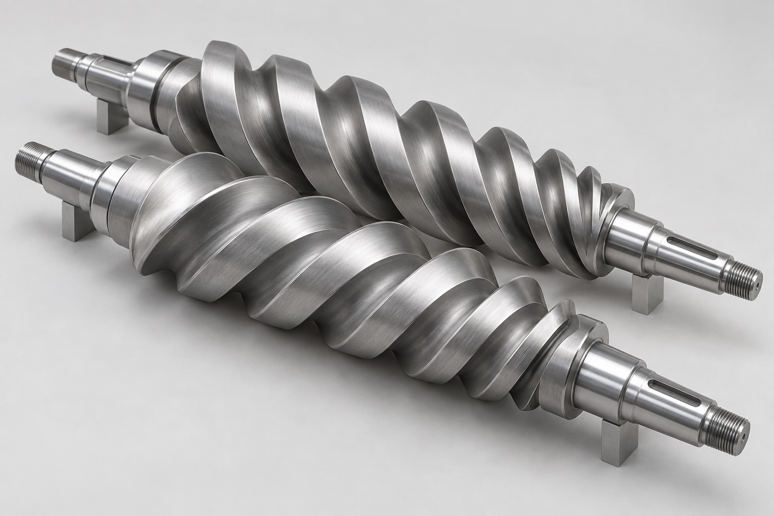 Vacuum pump rotors & housingsBalancing corrosion resistance, profile coverage and assembly clearanceAI illustration
View original ↗Dry screw rotor · AI illustration
Keeps the main forms such as paired screws, variable pitch and shaft ends, helping understand thickness distribution and fit clearance issues in surface treatment.
AI-generated · not a customer's actual part photo
To protect customer workpiece information, this image is an AI-generated illustration and does not show a real customer workpiece. It is for shape explanation only and is not a basis for manufacturing or acceptance.
Around twin-screw profiles, tooth tips and roots, and housing inner walls, evaluate electroless nickel coverage, media resistance and post-plating fit dimensions.
Conditions & key issues
- Corrosive gases & condensate
Describe gas composition, temperature, humidity and cleaning media, distinguishing dry running from condensing conditions.
- Complex profiles & precision fits
Focus on thickness differences at tooth tips, roots and end faces, and the effect of coating build-up on running clearance.
- Substrate & surface defects
Casting porosity, old coatings and local damage must be evaluated before pretreatment and sampling.
Solution & evaluation direction
- Evaluate the high-P electroless nickel direction
Choose candidate processes with the actual media and confirm corrosion resistance and adhesion with specimens.
- Agree measurement points by key profiles
Include thickness, tolerance, no-plating zones and post-machining allowance in the drawing evaluation.
- Move to volume after first-article confirmation
Recheck post-plating dimensions and appearance; rotor clearance and dynamic balance are checked per equipment requirements.
Related QA
Q: Can it be assembled directly after plating without checking dynamic balance?
A: Whether post-machining is needed and how to re-inspect should be confirmed per rotor drawings and equipment requirements. Thickness distribution, masking boundaries and post-treatment must all be included in dimensional and dynamic balance evaluation.
Q: Is high-P electroless nickel suitable for all corrosive gases?
A: Selection must consider gas composition, temperature, condensation conditions and cleaning media, then be verified with representative specimens.
Verification & communication points
Specific measurement points, conditions and criteria are confirmed per project. On small screens, swipe left and right to see the full table.
| Verification item | Verification content | Information to confirm |
|---|---|---|
| Thickness & dimensions | Thickness and post-plating dimensions at tooth tips, roots, end faces and key housing locations. | Provide measurement point drawings, target thickness, thickness tolerance and assembly clearance. |
| Media resistance | Specimen verification with agreed media and conditions, recording appearance and corrosion. | Specify media composition, concentration, temperature, time and criteria. |
| Adhesion & operation | Confirm the applicable adhesion method and recheck assembly and dynamic balance per equipment requirements. | Determined with substrate, thermal cycling conditions and equipment inspection specifications. |
 Semiconductor vacuum chambersStarting from cleanliness requirements to check process compatibility
View illustration in full size ↗Semiconductor vacuum chamber – engineering illustration
Uses the chamber openings, sealing faces and internal working surfaces to explain plating, cleaning and cleanliness evaluation for complex structures.
Original 3D engineering illustration
Explains structure and process evaluation only; it does not show actual customer parts and is not a basis for processing records, manufacturing or acceptance.
For vacuum reaction chambers, liners and related parts, surface treatment is evaluated together with cleaning, baking, particle and outgassing requirements.
Conditions & key issues
- Particles & surface residues
Focus on the effect of particles, residues and coating surface defects after cleaning on equipment processes.
- Vacuum & thermal cycling
Describe vacuum level, bake-out conditions and thermal cycling, and specify the outgassing verification method.
- Plasma & process atmosphere
Different process gases, plasma conditions and exposure locations must be confirmed separately.
Solution & evaluation direction
- Evaluate pretreatment by substrate
Check the grade and surface condition of aluminum alloy or other substrates, and dimensional and roughness requirements.
- Agree on a unified cleaning process
Write cleaning, packaging, bake-out and delivery condition into process and inspection requirements.
- Establish real-condition verification
Verify particles, outgassing and plasma compatibility separately, then confirm whether the coating is suitable.
Related QA
Q: Can a coating name alone indicate suitability for ultra-high vacuum?
A: Particles, outgassing and media compatibility must be confirmed with cleaning, bake-out and usage conditions. Suitability is based on verification results.
Q: How are post-plating dimensions controlled for thin-walled chambers?
A: First evaluate material, structure and machining state, then agree on dimensional allowance, fixturing method, coating thickness and post-plating measurement points.
Verification & communication points
Specific measurement points, conditions and criteria are confirmed per project. On small screens, swipe left and right to see the full table.
| Verification item | Verification content | Information to confirm |
|---|---|---|
| Particles & cleanliness | Confirm particles and surface residues with agreed cleaning, sampling and counting methods. | Specify particle size range, sampling location, cleaning process and limits. |
| Outgassing & vacuum | Conduct vacuum verification with the specified bake-out conditions and measurement method. | State target vacuum level, test temperature, background and judging method. |
| Dimensional & process compatibility | Recheck thin-walled structures, key dimensions and surface condition under the actual process atmosphere. | Provide material, key working surfaces, thermal cycling and process exposure conditions. |
 Extrusion dies & forming partsEvaluating wear and release with material and temperature
View illustration in full size ↗Forming mold – engineering illustration
Uses the flow channel, die lips and key working surfaces of a long die to discuss coating thickness, surface condition and dimensional control along the length.
Original 3D engineering illustration
Explains structure and process evaluation only; it does not show actual customer parts and is not a basis for processing records, manufacturing or acceptance.
Starting from wear and sticking at die lips, flow channels and forming surfaces, discuss electroless nickel or composite coating solutions.
Conditions & key issues
- Working surface wear & scoring
Resin, fillers, temperature and operating method affect wear patterns and must be analyzed with actual conditions.
- Sticking & release
Describe the sticking substance, cleaning method and where release problems occur, rather than judging the effect by water contact angle alone.
- Long dimensions & die opening tolerance
Key points to confirm are coating thickness and dimensional allowance at die lips, flow channels, edges and along the length.
Solution & evaluation direction
- Compare processes by performance goals
Evaluate the applicable directions of electroless nickel and composite coatings, trading off wear resistance, friction reduction and release goals.
- Check heat treatment limits
First confirm die material, heat treatment state and allowable temperature, then discuss post-treatment.
- Confirm effect with specimens and trial molding
Combine release, wear and dimensional inspection; for old dies, evaluate stripping and repair allowance first.
Related QA
Q: Can high hardness and good release be achieved at the same time?
A: This must be evaluated with resin, temperature and friction conditions, and the coating system determined through specimens and trial molding. Different performance goals may require trade-offs.
Q: Can old dies be stripped and retreated?
A: First inspect material, old coating, wear and remaining dimensional allowance, then decide the stripping and repair method. After treatment, key dimensions and working surfaces must be re-inspected.
Verification & communication points
Specific measurement points, conditions and criteria are confirmed per project. On small screens, swipe left and right to see the full table.
| Verification item | Verification content | Information to confirm |
|---|---|---|
| Thickness & working surfaces | Recheck thickness, dimensions and roughness along the die length and key flow channels. | Provide outer dimensions, weight, racking restrictions and measurement point requirements. |
| Hardness & wear resistance | Confirm hardness and wear test conditions separately, recording as-plated or heat-treated state. | Agree on measurement load, counterpart, temperature and wear criteria. |
| Actual release performance | Run specimens/trial molding with the agreed resin or compound, recording release force or residue. | Specify material formulation, temperature, cycle count and cleaning method. |
 Control valve plugs & sealing seatsAttending to media, erosion and sealing surfaces at once
View illustration in full size ↗Valve spool and sleeve – engineering illustration
Uses the steps, ports and mating diameters of a valve spool and sleeve to explain the evaluation of wear resistance, film thickness and post-plating fit dimensions.
Original 3D engineering illustration
Explains structure and process evaluation only; it does not show actual customer parts and is not a basis for processing records, manufacturing or acceptance.
Considering pressure, differential pressure, media and particle conditions, we evaluate how coating thickness, surface quality and post-treatment affect sealing performance.
Conditions & key issues
- Erosion & local damage
Describe flow velocity, pressure difference, solid particles and failure locations, distinguishing wear, erosion and corrosion.
- Thickness & fit dimensions
Coating build-up affects plug–seat fit, so machining allowance and sealing surface inspection conditions must be reserved.
- Special media & material requirements
Sour (sulfur-containing) conditions require evaluating the overall substrate and surface treatment solution against applicable material requirements.
Solution & evaluation direction
- Confirm coating direction by conditions
Compare corrosion and wear goals of candidate electroless nickel processes and agree on thickness and key surfaces.
- Evaluate adhesion & post-treatment
Discuss the process by substrate, thickness and service conditions, and verify bonding between coating and substrate.
- Verify coating and sealing separately
First inspect thickness, roughness and dimensions, then conduct assembly sealing and cycle tests as agreed.
Related QA
Q: Can a coating replace the sour-service material selection requirements for the substrate?
A: The complete solution should be evaluated against applicable material specifications, media, temperature and pressure; a coating cannot be a basis for skipping substrate selection and verification.
Q: How is a thick coating confirmed as suitable for sealing surfaces?
A: Beyond thickness and adhesion, roughness, dimensions and sealing performance after assembly must be verified; service life is confirmed through agreed cycle tests.
Verification & communication points
Specific measurement points, conditions and criteria are confirmed per project. On small screens, swipe left and right to see the full table.
| Verification item | Verification content | Information to confirm |
|---|---|---|
| Thickness & adhesion | Measure thickness on key surfaces and choose an applicable adhesion method by substrate and coating. | Specify thickness tolerance, sampling plan, test method and criteria. |
| Working surfaces & fit | Confirm roughness, geometric dimensions and coating condition after post-machining. | Provide sealing surface drawings, tolerances and post-machining arrangements. |
| Sealing & cycling | Conduct seal tests and cycle durability verification separately under agreed conditions. | Specify media, temperature, pressure/pressure difference, cycles and leakage criteria. |
 Deep-bore bushings & micro sleevesConfirming coverage quality from in-bore flow and venting
View illustration in full size ↗Deep-bore sleeve – engineering illustration
Uses the sleeve bore and end steps to discuss coverage inside the bore, venting and inspection of key measuring points.
Original 3D engineering illustration
Explains structure and process evaluation only; it does not show actual customer parts and is not a basis for processing records, manufacturing or acceptance.
Based on hole diameter, depth and through/blind structure, evaluate fixturing, solution flow, venting and thickness verification at different locations.
Conditions & key issues
- Solution exchange deep in the bore
Bore shape and flow conditions affect deposition; provide hole diameter, depth and cross-hole structure.
- Bubbles & local skip plating
Racking orientation and venting conditions must be considered together with the workpiece structure.
- Post-plating bore diameter & sliding
Check the effect of build-up on bore diameter, as well as counterpart, lubrication and roughness requirements.
Solution & evaluation direction
- Evaluate fixtures by hole shape
Discuss racking, circulation and venting, first confirming solution access inside the bore.
- Verify thickness with the first article
Measure at representative locations such as entrance, middle and bottom, using sectioned specimens if necessary.
- Agree on batch inspection methods
Determine inspection and sampling methods with hole diameter and probe accessibility, and recheck post-plating dimensions.
Related QA
Q: Can electroless plating guarantee equal thickness inside and outside all deep holes?
A: Thickness distribution is affected by hole shape, solution flow and venting, and must be confirmed by measuring the first article at different locations. Equal thickness cannot be guaranteed by coating type name alone.
Q: How is the inner wall of a small hole inspected?
A: The first article can be sectioned to observe the coating at different locations; batch inspection is determined by hole diameter, probe accessibility and sampling plan. Weighing results cannot represent coverage of all bore walls.
Verification & communication points
Specific measurement points, conditions and criteria are confirmed per project. On small screens, swipe left and right to see the full table.
| Verification item | Verification content | Information to confirm |
|---|---|---|
| Thickness distribution in the bore | The first article is sectioned or measured by an applicable method at the entrance, middle and bottom. | Provide hole shape drawings, thickness targets and representative measurement points. |
| Appearance & continuity | Choose an observation method by accessibility and check local coverage with representative specimens. | Agree on observation scope, defect criteria and sample size. |
| Dimensions & sliding | Recheck bore diameter, roundness and roughness; if friction reduction is a goal, verify with the agreed counterpart. | Specify pre/post-plating dimensions, lubrication, load and motion conditions. |
Related test charts & test conditions
Application needs & evaluation examples
Starting from current processes, failure problems and specific conditions, view candidate coatings and verification points.
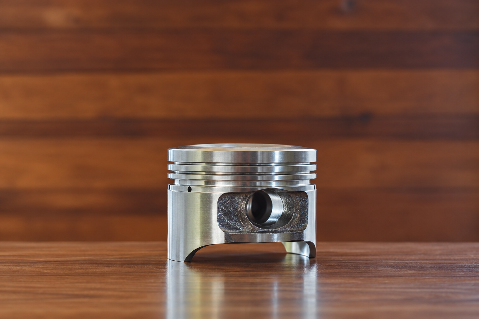 Wear evaluation of aluminum sliding partsFinding an alternative to the original coating under strict dimensional requirements
Enlarge image ↗Aluminum sliding part image
Around the part's sliding contact surfaces and fit locations, confirm the areas to be plated, thickness allowance and wear inspection locations.
Company M needed to replace its original coating because the processor stopped offering it. The parts are aluminum with strict dimensional accuracy; a general electroless nickel coating was tried but wore away in sliding tests. The evaluation focused on wear resistance in contact with the counterpart material and on post-plating dimensions.
Conditions & key issues
- Original treatment discontinued
An alternative process that continues to meet the part's requirements is needed.
- Strict dimensional accuracy requirements
The company considered that electroplating could not meet existing dimensional requirements, so coating thickness and fit dimensions must be evaluated together.
- Trial coating wore away
General electroless nickel did not meet wear requirements in the existing sliding test; actual contact conditions need rechecking.
Solution & evaluation direction
- Plan to evaluate a wear-resistant electroless coating
Ni-P-B electroless coating is listed as a candidate, compared under the same conditions with the general electroless nickel already trialed.
- Plan to check thickness & dimensional allowance
Determine the acceptable thickness range and measurement points from the key fit dimensions.
- Plan to reproduce the sliding test
Use representative counterpart materials and loads, recording wear of the coating and counterpart.
Related QA
Q: General electroless nickel wore away—is increasing thickness enough?
A: First evaluate with wear location, counterpart and dimensional allowance, then compare the feasibility of adjusting thickness versus switching to a candidate coating.
Q: Can the original treatment's dimensional requirements be used directly?
A: They can be a starting point; it must also be clarified whether the original requirements are pre- or post-plating dimensions, and the new solution's thickness and inspection locations confirmed accordingly.
Verification & communication points
Specific measurement points, conditions and criteria are confirmed per project. On small screens, swipe left and right to see the full table.
| Verification item | Verification content | Information to confirm |
|---|---|---|
| Sliding wear | Compare wear and remaining coating of candidate coatings in the same sliding test. | Counterpart, load, speed, lubrication state, cycle count and failure criteria. |
| Thickness & fit | Check thickness on key contact surfaces and post-plating fit dimensions. | Part drawings, pre-plating dimensions, fit tolerances and available thickness allowance. |
| Substrate & coating condition | Confirm aluminum pretreatment, coating adhesion and surface condition after testing. | Aluminum alloy grade, original treatment information, trial records and failed samples. |
Image & data notes
Images are AI-enhanced remakes of the original pictures, used to illustrate the application scenario.
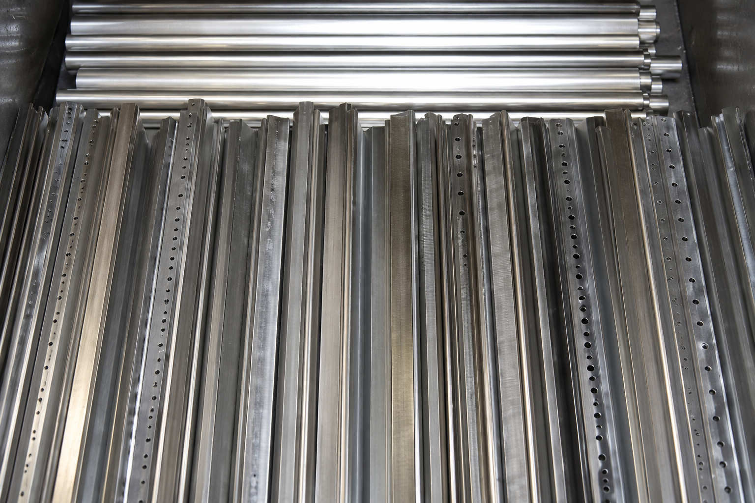 Anti-galling evaluation of aluminum sliding partsChecking coating suitability around high contact pressure and repeated sliding
Enlarge image ↗Aluminum sliding part image
Focusing on the sliding contact area to discuss fit type, load locations and where galling occurs.
Company I's aluminum sliding parts have high contact pressure and many sliding cycles, and the bare substrate easily galls. To maintain dimensional accuracy, a 10 μm electroless nickel coating was used, but galling still occurred; the company wanted an electroless coating better suited to these conditions.
Conditions & key issues
- Repeated sliding under high surface pressure
High contact pressure and many sliding cycles are key service conditions in this case.
- Galling still occurred with the existing coating
The 10 μm electroless nickel coating already trialed did not pass the company's usage criteria.
- Anti-galling and dimensions both matter
Candidate coatings must be compared under the existing dimensional requirements, not by hardness alone.
Solution & evaluation direction
- Plan to evaluate Ni-P-B as a candidate coating
Around anti-galling needs, compare candidate electroless coatings under actual contact conditions.
- Plan to check contact surfaces & fit
Check counterpart material, contact surface condition and post-plating clearance, and define test conditions.
- Plan cyclic sliding verification
Record cycles to galling, friction changes and surface damage, then judge whether the solution is suitable.
Related QA
Q: Can 10 μm be used directly as the new solution's thickness?
A: 10 μm is the thickness of the solution already trialed; the new solution must be reconfirmed with dimensional allowance, coverage requirements and sliding verification.
Q: Can comparing coating hardness alone determine anti-galling effectiveness?
A: Performance under actual surface pressure, counterpart, lubrication and sliding cycles should be compared, with galling and surface damage records as the basis of evaluation.
Verification & communication points
Specific measurement points, conditions and criteria are confirmed per project. On small screens, swipe left and right to see the full table.
| Verification item | Verification content | Information to confirm |
|---|---|---|
| Cyclic sliding | Record galling, friction changes and coating damage within the specified cycles. | Contact pressure, sliding stroke, speed, cycle count and lubrication state. |
| Fit dimensions | Check thickness, dimensions and assembly clearance on key surfaces. | Aluminum grade, fit drawings, tolerances and allowable thickness range. |
| Failure comparison | Compare galling locations of the existing 10 μm coating and candidate samples. | Existing test conditions, rejection criteria and failed samples or photos. |
Image & data notes
Images are AI-enhanced remakes of the original pictures, used to illustrate the application scenario.
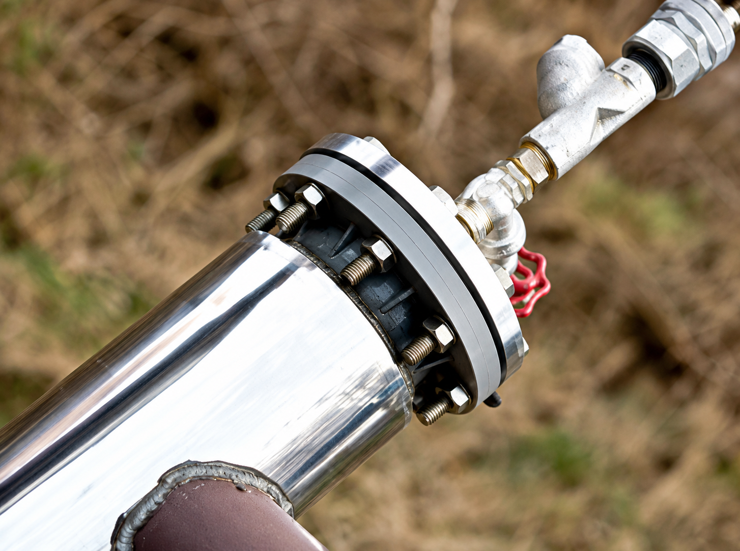 Durability evaluation of small-hole sliding areas in aluminumFor an automated line, evaluating in-bore wear resistance and maintenance intervals
Enlarge image ↗Metal wire contact part image
Using the contact location in the φ3 × 15 mm through-hole, discuss inner-wall plating, bore diameter change and in-bore inspection methods.
Company C's aluminum parts wear easily at the sliding area in contact with metal wire. The parts are moving from a manual line to an automated line, and the customer set a target of about 2× the original durability to reduce maintenance frequency. The substrate cannot be changed, and the area to treat is the inner wall of a φ3 × 15 mm through-hole.
Conditions & key issues
- Area in contact with metal wire wears easily
Current parts have a short life; the sliding contact area is the focus of durability evaluation.
- Automated line requires a longer life target
About 2× durability is the customer's requirement; the baseline life and failure criteria must be defined first.
- Aluminum substrate and small bore inner wall are constrained
The substrate cannot be changed; the area to treat is concentrated on the inner wall of a φ3 × 15 mm through-hole.
Solution & evaluation direction
- Plan to evaluate an in-bore wear-resistant electroless coating
Ni-P-B electroless coating is the candidate, evaluated with aluminum and metal wire contact conditions.
- Plan to confirm in-bore coverage & dimensions
Evaluate fixturing, solution flow and in-bore inspection methods, and check post-plating bore allowance.
- Plan to set up a life comparison test
Using the current part as baseline, compare wear and maintenance intervals under the corresponding automated line conditions.
Related QA
Q: How do we judge whether we are close to the ~2× durability target?
A: First agree on the current part's life baseline, operating conditions and failure criteria, then compare candidate samples' life on the same basis.
For in-bore inspection methods see: Deep-bore bushings & micro sleeves · related Q&A ↗
Verification & communication points
Specific measurement points, conditions and criteria are confirmed per project. On small screens, swipe left and right to see the full table.
| Verification item | Verification content | Information to confirm |
|---|---|---|
| In-bore coverage | Check coverage and thickness at agreed locations such as hole entrance, middle and exit. | Hole structure drawing, target thickness, allowable sampling method and measurement points. |
| Post-plating bore diameter | Check the bore diameter after inner-wall plating and its fit with the metal wire. | Original bore diameter, tolerance, metal wire size and contact location. |
| Durability & maintenance | Record wear, time to failure and interval until maintenance conditions are reached. | Metal wire material, speed, tension or load, current life and automated line takt. |
Image & data notes
Images are AI-enhanced remakes of the original pictures, used to illustrate the application scenario.
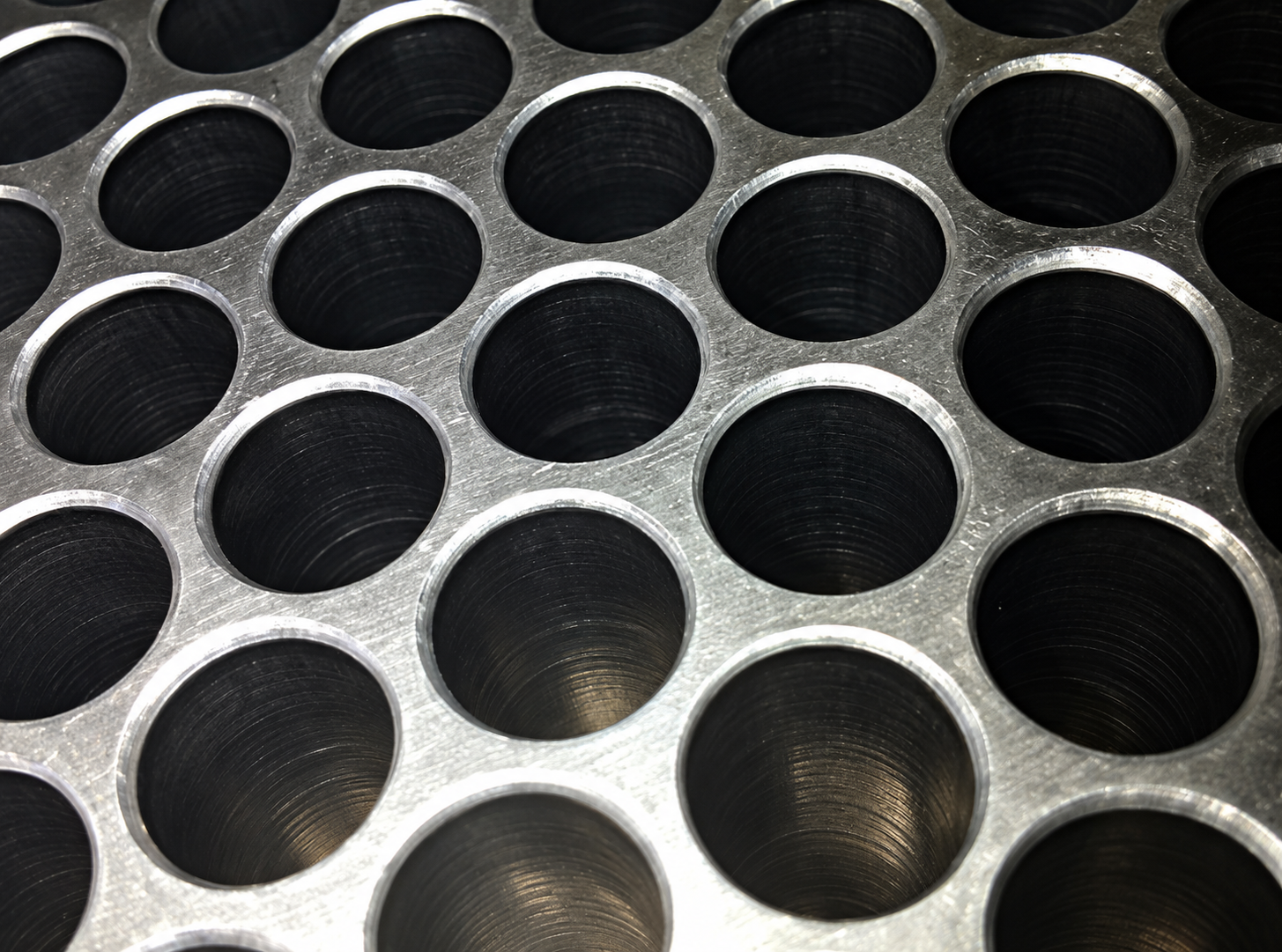 Life evaluation of high-temperature resin molding diesAt about 300 ℃, evaluating wear resistance and material compatibility
Enlarge image ↗Resin molding die image
Around resin contact surfaces and working areas where resin flows, discuss wear inspection locations and post-plating dimensional requirements.
Company B's resin molding dies are used at about 300 ℃, and resin flow wears the die body. SUS420J2 was chosen for corrosion resistance at high cost, and the company wanted to extend service life as much as possible through surface treatment.
Conditions & key issues
- Resin flow wear at high temperature
A service temperature of about 300 ℃ and resin contact together form the wear evaluation conditions.
- Corrosion resistance requirements must be retained
The original solution chose SUS420J2 for corrosion resistance, so surface treatment must be evaluated with that requirement.
- High die cost, life extension desired
Extending service life is the goal; a comparison should be built from wear and maintenance records of the current die.
Solution & evaluation direction
- Plan to evaluate a wear-resistant electroless coating
Ni-P-B electroless coating is listed as a candidate, with pre- and post-treatment evaluated for the SUS420J2 substrate.
- Plan to check temperature & dimensional limits
Distinguish service temperature from post-plating heat treatment conditions, and check die condition, dimensions and heat treatment limits.
- Plan representative molding verification
Record working surface wear, surface condition and maintenance intervals with the agreed resin and temperature.
Related QA
Q: With a service temperature of about 300 ℃, can the heat treatment temperature be set directly from it?
A: They are different conditions. Heat treatment arrangements should be confirmed separately with die material condition, dimensional requirements and the candidate coating.
Q: How should life extension be evaluated?
A: Using the current die as a control, record wear, molding quality and maintenance intervals under the same resin and molding conditions, then evaluate the change in life.
Verification & communication points
Specific measurement points, conditions and criteria are confirmed per project. On small screens, swipe left and right to see the full table.
| Verification item | Verification content | Information to confirm |
|---|---|---|
| High-temperature wear | Record working surface wear under representative molding conditions. | Resin type, service temperature, run time or cycle count and wear limits. |
| Dimensions & surface | Check post-plating key dimensions, surface condition and changes after heat treatment. | Die drawings, SUS420J2 material condition, thickness and heat treatment limits. |
| Corrosion resistance & maintenance | Check corrosion and maintenance needs with service and cleaning conditions. | Media to protect against, cleaning method and current maintenance records. |
Image & data notes
Images are AI-enhanced remakes of the original pictures, used to illustrate the application scenario.
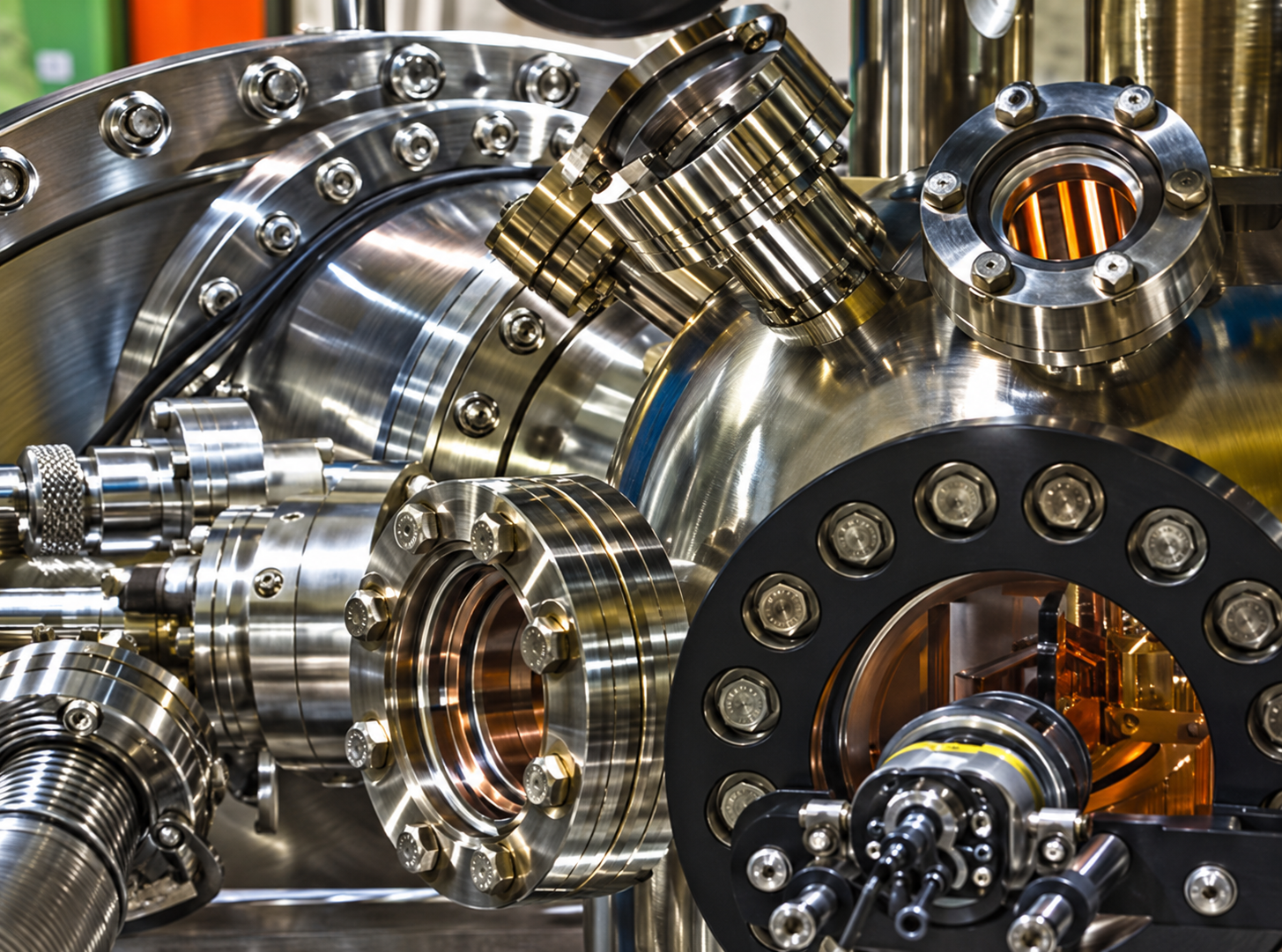 Corrosion & anti-adhesion evaluation in vacuum environmentsChecking halogen gas corrosion and foreign-matter-induced galling together
Enlarge image ↗Vacuum equipment part image
Using gas exposure locations and sliding contact areas in the equipment, discuss corrosion resistance and foreign matter adhesion separately.
Company A's products are corroded by halogen gases in a vacuum environment. Foreign matter adhesion can also cause galling in sliding areas; the company wanted a surface treatment that resists foreign matter adhesion, or keeps sliding even after adhesion.
Conditions & key issues
- Halogen gas corrosion
Gas type and actual exposure conditions must be specified to determine the scope of corrosion evaluation.
- Foreign matter adhesion affects sliding
Deposits may enter contact areas and trigger galling; their source and nature must be checked.
- Corrosion resistance and anti-adhesion must both be met
Improving sliding performance alone cannot directly determine overall suitability for these conditions.
Solution & evaluation direction
- Plan to evaluate Ni-P/PTFE composite coating
The composite coating is listed as a candidate for anti-adhesion and sliding, with its media compatibility confirmed separately.
- Plan to separate corrosion and galling verification
Set up gas exposure and sliding-with-deposits evaluations separately to avoid mixing judging criteria.
- Plan to check actual vacuum conditions
Confirm samples and verification methods with temperature, vacuum level and cleaning process.
Related QA
Q: How are halogen corrosion and foreign-matter galling evaluated separately?
A: Record corrosion and coating condition after the agreed gas exposure, and sliding, galling and surface damage under actual deposit conditions, separately; both results together are used to evaluate the conditions.
Q: Is it enough to look at friction performance of clean samples?
A: Sliding and galling under actual deposit conditions must also be evaluated, recording the effect of deposits on working surfaces.
For general evaluation of media suitability see: Vacuum pump rotors & housings · related Q&A ↗
Verification & communication points
Specific measurement points, conditions and criteria are confirmed per project. On small screens, swipe left and right to see the full table.
| Verification item | Verification content | Information to confirm |
|---|---|---|
| Gas exposure | Observe corrosion, appearance and coating condition under the agreed atmosphere. | Gas composition, temperature, vacuum level, exposure time and criteria. |
| Foreign matter & sliding | Compare adhesion and galling or damage in sliding areas after adhesion. | Foreign matter composition, adhesion location, contact load, stroke and counterpart material. |
| Cleaning & surface condition | Check surface condition after cleaning and subsequent operating requirements. | Cleaning media, method, frequency and equipment requirements to be met. |
Image & data notes
Images are AI-enhanced remakes of the original pictures, used to illustrate the application scenario.
 Anti-galling evaluation of semiconductor equipment boltsChecking candidate surface treatments through fastening and removal
Enlarge image ↗Bolt and nut image
Around thread fit and fastening contact areas, confirm plating scope, fit dimensions and assembly/disassembly test methods.
Company K's bolts for semiconductor manufacturing equipment were originally electroplated with nickel, but galled and seized in service. The company wanted a surface treatment that prevents galling while allowing easy fastening and removal.
Conditions & key issues
- Existing electroplated nickel solution seized
Galling locations and service conditions must be confirmed with failed bolts and mating parts.
- Requirements for both fastening and removal
Not only the tightening process, but removal performance after use must also be recorded.
- Equipment conditions still to be detailed
The equipment use is known, but bolt material, temperature, mating parts and assembly frequency still need confirmation.
Solution & evaluation direction
- Plan to evaluate a low-friction composite coating
Ni-P/PTFE composite coating is listed as a candidate, comparing assembly/disassembly performance with the current electroplated nickel solution.
- Plan to check thread thickness & fit
Evaluate post-plating assembly and inspection requirements with thread specification, tolerances and plating area.
- Plan repeated assembly/disassembly tests
Record tightening, removal and galling under agreed fastening conditions, then judge the solution's suitability.
Related QA
Q: Can the original tightening torque be kept after changing the coating?
A: Fastening requirements should be confirmed through assembly tests of the candidate surface, checking torque, mating parts and the connection state specified by the equipment.
Q: How do we confirm the anti-galling and easy-removal goals?
A: After representative service conditions, conduct assembly/disassembly comparisons, recording removal torque, number of seizures and thread damage, judged per agreed criteria.
Verification & communication points
Specific measurement points, conditions and criteria are confirmed per project. On small screens, swipe left and right to see the full table.
| Verification item | Verification content | Information to confirm |
|---|---|---|
| Assembly/disassembly & galling | Record seizure, damage and handling performance after repeated assembly/disassembly. | Bolt and mating part materials, assembly cycles, temperature and lubrication state. |
| Fastening conditions | Record tightening and removal torque and the connection state required by the equipment. | Fastening specifications, preload requirements, service duration and test procedure. |
| Thread fit | Check post-plating thread dimensions, go/no-go and key surfaces. | Thread specification, tolerance, target thickness and no-plating zones. |
Image & data notes
Images are AI-enhanced remakes of the original pictures, used to illustrate the application scenario.
The above are typical application references. Specific coatings, chemicals and processes must be confirmed with substrate, structure and service conditions; project results are verified on actual workpieces and agreed tests.
Start the conversation from your needs
If you have parts, first describe the substrate, quantity and goals; if purchasing chemicals, add your current process, bath size and expected usage.