Processing customers, start here
Improve resistance to indentation
A specific composite coating: HV550–600 as-plated; HV1000–1200 after heat treatment.
This record applies to a SiC composite coating with 300°C heat treatment; holding time, test load, etc. need confirmation, and it does not represent all processes. Hardness is not wear life; please state separately whether the substrate allows heat treatment.
Tell our engineers your requirements
Enter substrate, quantity and performance targets; if you don't know the specific metrics, you can describe the problem you face.
Detailed test data · expand test conditions, historical data and interpretation
Conclusions first
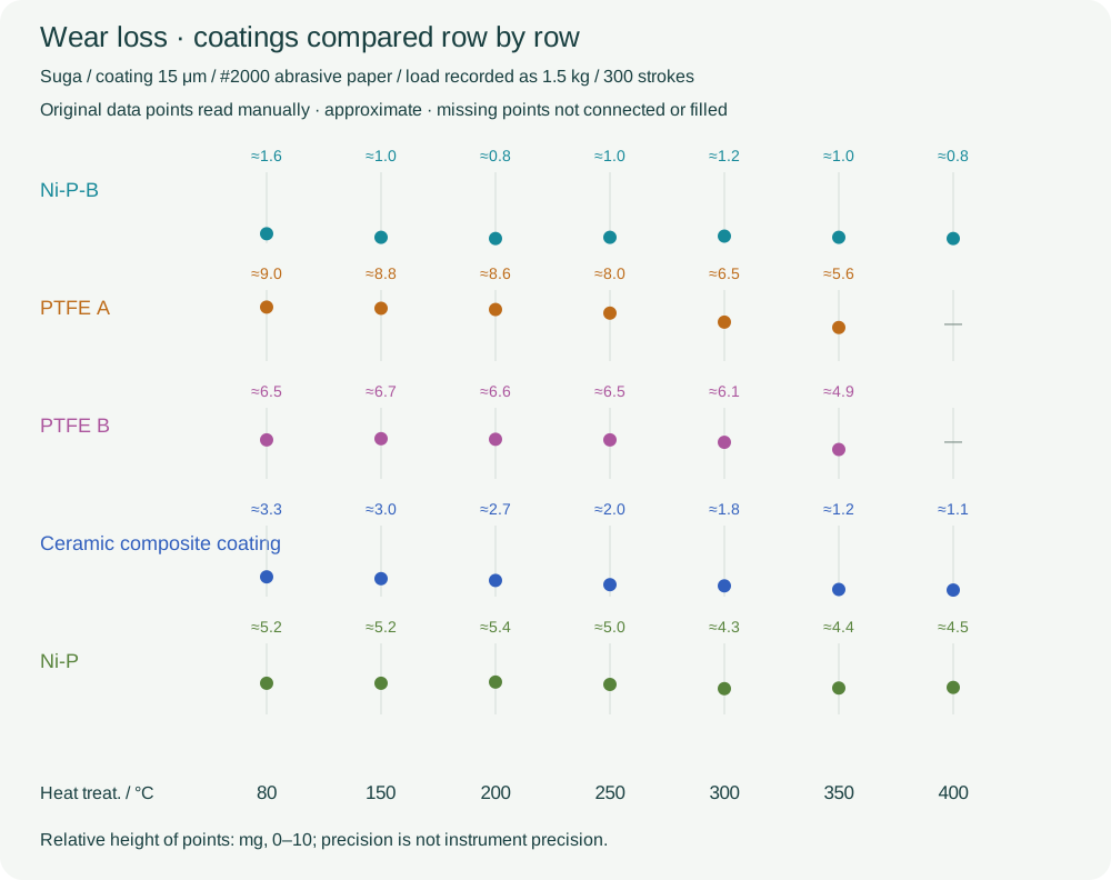
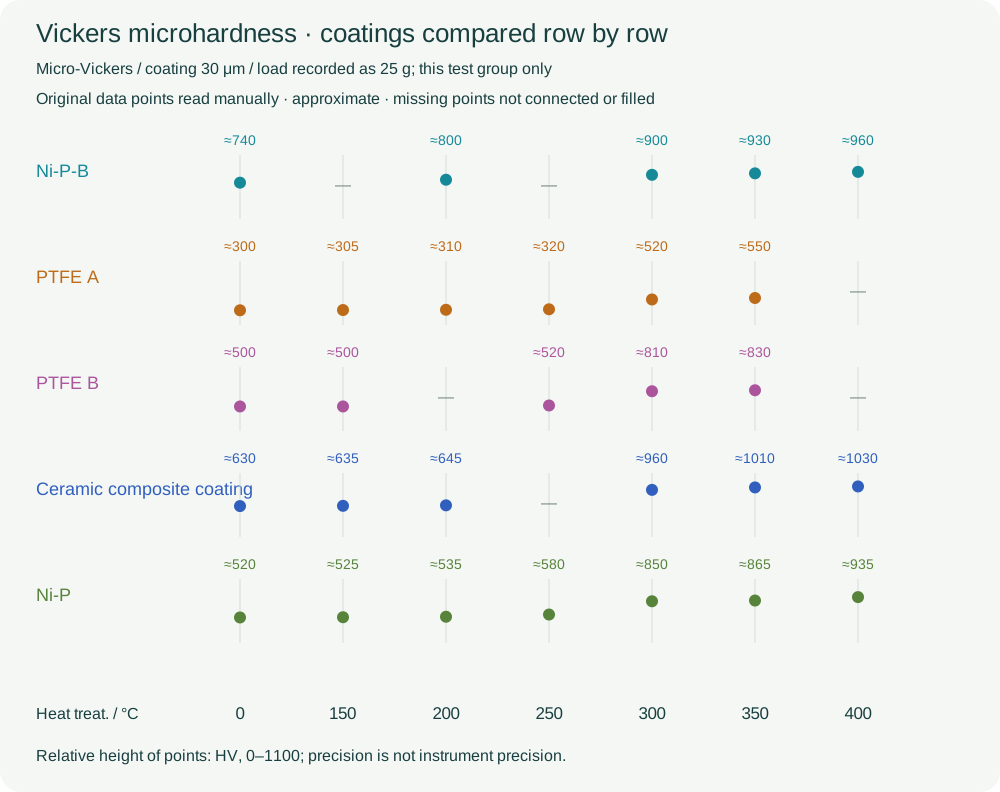
The wear test used a 15 μm coating; the hardness test used 30 μm—these are two separate experiments.
Complete wear and hardness curves are listed separately; confirm the test conditions first, then compare trends at the same heat-treatment temperature.
Hardness is not the only indicator of wear resistance; the counterpart, load and lubrication conditions must be considered too.
Test conditions
Wear test | Suga
- Standard / equipment
- Suga abrasion tester
- Medium
- Dry environment
- Load
- 1.5 kg (load notation as in source)
- Counterpart
- #2000 waterproof abrasive paper
- Thickness
- 15 μm
- Heat treatment
- Heat-treatment temperature on the curve's horizontal axis
Wear area 30 × 12 mm; 300 reciprocations. Heat-treatment temperature on the curve; comparisons are limited to this group's test conditions.
Hardness test | Vickers microhardness
- Standard / equipment
- Vickers microhardness tester
- Load
- 25 g (load as labeled in source)
- Counterpart
- No sliding counterpart applicable
- Thickness
- 30 μm
- Heat treatment
- Heat-treatment temperature on the curve's horizontal axis
Wear & hardness: read the two tests separately
Redrawn values are manual readings of marked points in the source charts and cannot replace original measurement data. "—" means no corresponding marked point; 0°C follows the original chart's starting-point notation and does not mean actual 0°C heat treatment. The ceramic composite coating is read as a separate specimen.
On mobile, swipe the chart left/right; tap a chart to open the large image.
On mobile, swipe the chart left/right; tap a chart to open the large image.
View point-by-point readings of the redrawn wear and hardness charts
The following are approximate manual image readings; "—" means no corresponding marked point in the original chart, not zero. Actual marked points of each curve are kept without interpolation.
Wear loss / mg · coating 15 μm
| Coating / heat-treatment temperature °C | 80 | 150 | 200 | 250 | 300 | 350 | 400 |
|---|---|---|---|---|---|---|---|
| Ni-P-B | ≈ 1.6 | ≈ 1.0 | ≈ 0.8 | ≈ 1.0 | ≈ 1.2 | ≈ 1.0 | ≈ 0.8 |
| PTFE A | ≈ 9.0 | ≈ 8.8 | ≈ 8.6 | ≈ 8.0 | ≈ 6.5 | ≈ 5.6 | — |
| PTFE B | ≈ 6.5 | ≈ 6.7 | ≈ 6.6 | ≈ 6.5 | ≈ 6.1 | ≈ 4.9 | — |
| Ceramic composite coating | ≈ 3.3 | ≈ 3.0 | ≈ 2.7 | ≈ 2.0 | ≈ 1.8 | ≈ 1.2 | ≈ 1.1 |
| Ni-P | ≈ 5.2 | ≈ 5.2 | ≈ 5.4 | ≈ 5.0 | ≈ 4.3 | ≈ 4.4 | ≈ 4.5 |
Vickers hardness / HV · coating 30 μm
| Coating / heat-treatment temperature °C | 0 | 150 | 200 | 250 | 300 | 350 | 400 |
|---|---|---|---|---|---|---|---|
| Ni-P-B | ≈ 740 | — | ≈ 800 | — | ≈ 900 | ≈ 930 | ≈ 960 |
| PTFE A | ≈ 300 | ≈ 305 | ≈ 310 | ≈ 320 | ≈ 520 | ≈ 550 | — |
| PTFE B | ≈ 500 | ≈ 500 | — | ≈ 520 | ≈ 810 | ≈ 830 | — |
| Ceramic composite coating | ≈ 630 | ≈ 635 | ≈ 645 | — | ≈ 960 | ≈ 1010 | ≈ 1030 |
| Ni-P | ≈ 520 | ≈ 525 | ≈ 535 | ≈ 580 | ≈ 850 | ≈ 865 | ≈ 935 |
Wear specimens 15 μm, hardness specimens 30 μm; point heights are only for comparison within each chart, and the two charts cannot be cross-converted into service life. The original charts are kept below for checking.
Data & interpretation
What each test measures
The table scrolls horizontally; the first column keeps the comparison items.
| Test | Result metric | Coating thickness |
|---|---|---|
| Suga abrasion | Mass loss, mg; smaller means less wear in this test | 15 μm |
| Vickers microhardness | Vickers hardness, HV; not wear life | 30 μm |
Both tests use heat-treatment temperature as the horizontal axis, but coating thickness and test method differ. The curves show comparative trends; image readings are not treated as original measurements or contract specifications.
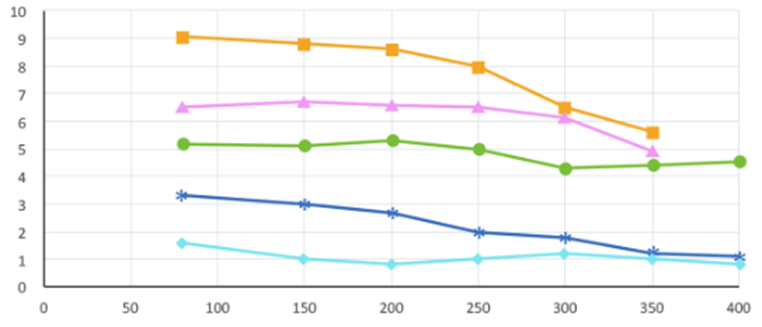
Horizontal axis: heat-treatment temperature (°C); vertical axis: wear loss (mg). Cyan is Ni-P-B, orange PTFE A, pink PTFE B, blue the ceramic composite coating, green Ni-P. Curves are only for comparison under the same group's conditions and cannot be converted into service life.
View full-size image ↗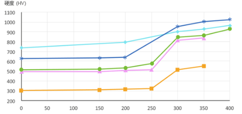
Horizontal axis: heat-treatment temperature (°C); vertical axis: Vickers hardness (HV). Colors match the wear chart; hardness specimens are 30 μm and wear specimens 15 μm—two separate tests.
View full-size image ↗Test charts & test conditions
View charts, methods and conditions test by test. Vector charts can be clicked to enlarge; each data group applies only to the corresponding specimens and test conditions.
Oil-fed reciprocating wear: coating and counterpart wear
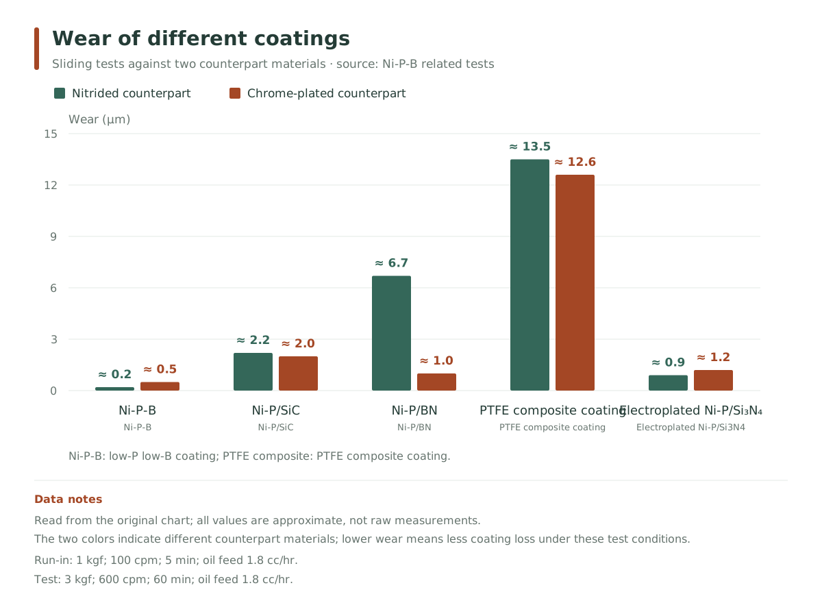
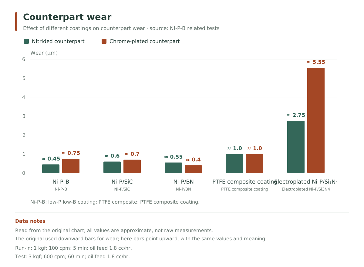
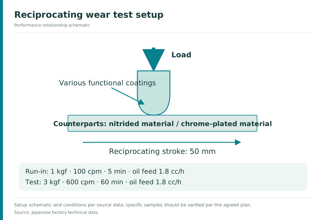
Test method & conditions
- Running-in stage
- 1 kgf;100 cpm;5 min
- Main test
- 3 kgf;600 cpm;60 min
- Oil feed in both stages
- Both 1.8 cc/h
- Counterpart treatment
- Nitriding / chrome plating
Japanese factory test values, not guaranteed values. Bar lengths are read from the original charts. The two result charts show coating wear and counterpart wear respectively; this group’s conditions are used on their own.
Abrasive wear test with hard chrome comparison
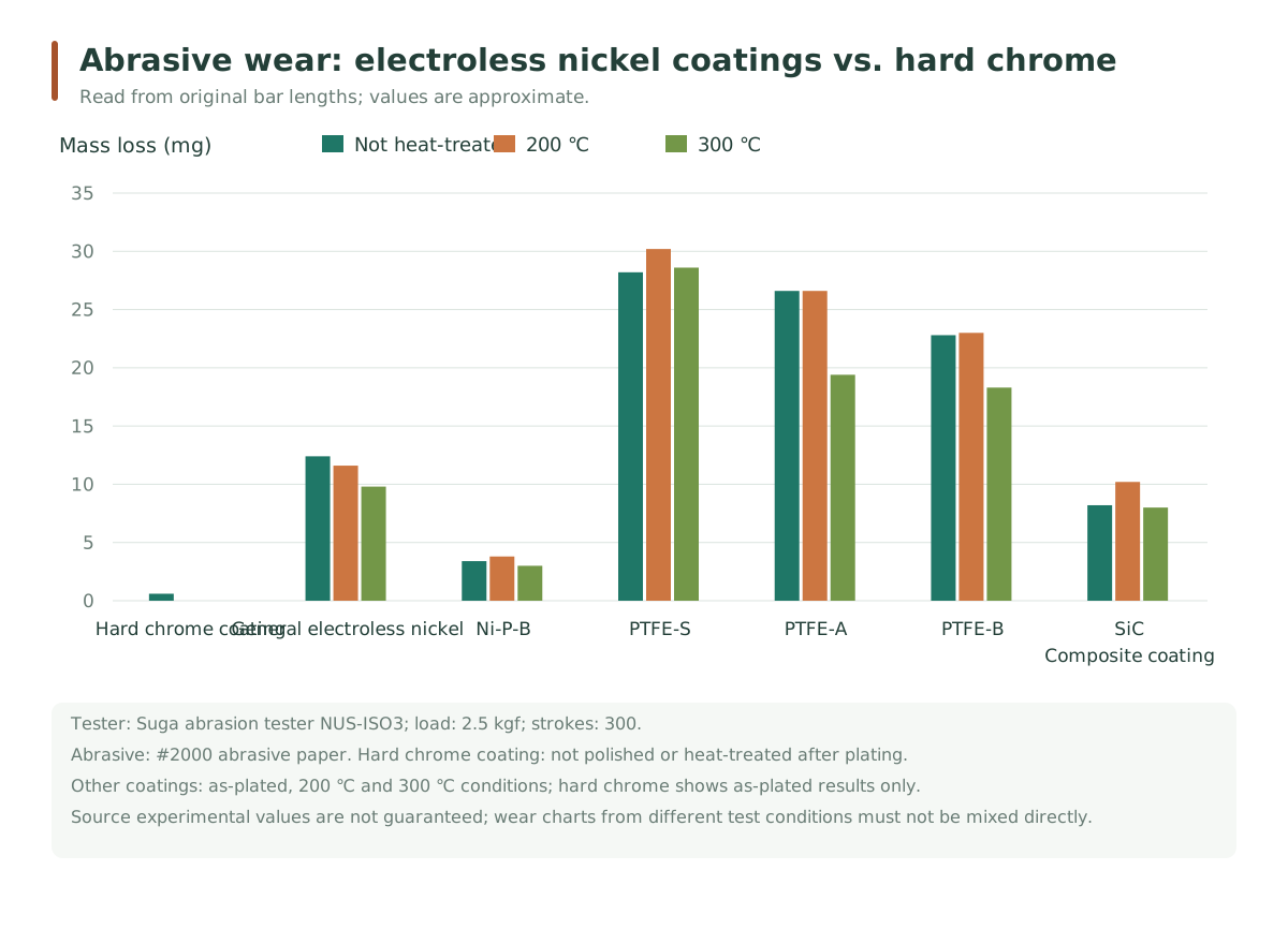
Test method & conditions
- Standard cited by source
- JIS H 8503 (as cited by source)
- Test equipment
- Suga NUS-ISO3 (as labeled in source chart)
- Load / reciprocations
- 2.5 kgf / 300 cycles
- Abrasive
- #2000 abrasive paper
- Hard chrome specimen
- Not ground after plating; not heat-treated
- Other coating conditions
- Not heat-treated / 200 ℃ / 300 ℃
Japanese factory test values, not guaranteed values. Bar lengths are read from the original chart. This 2.5 kgf test and the existing 1.5 kg temperature–wear test on this page are shown separately, each with its original conditions.
Source
General electroless nickel: heat-treatment temperature vs. hardness
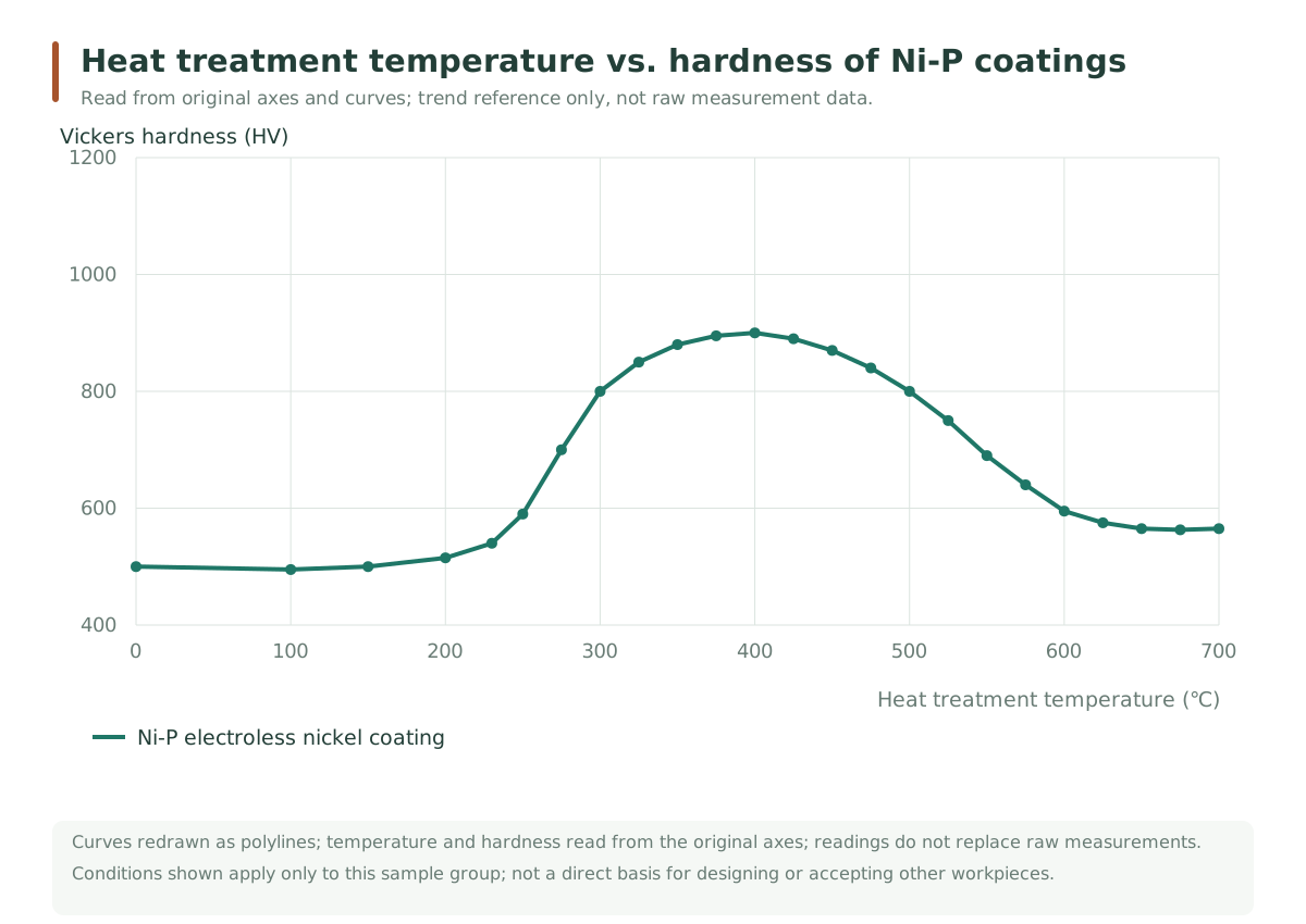
Test method & conditions
- Specimen
- General electroless nickel Ni-P
- Heat-treatment temperature
- Horizontal axis 0–700 ℃, see chart
Japanese factory test values, not guaranteed values. The curve is read from the original chart to illustrate the heat-treatment trend; it cannot be used directly as an acceptance curve for current products.
Abrasive paper wear method diagram
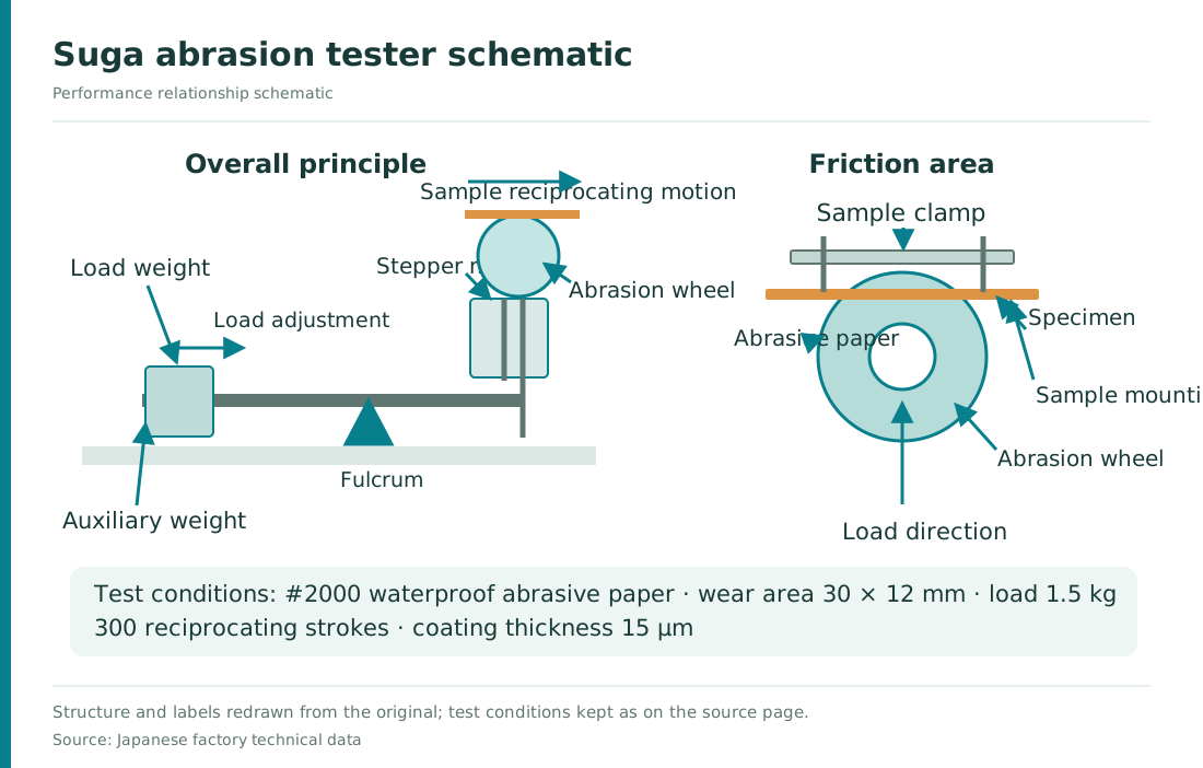
Test method & conditions
- Nature of method
- Setup structure diagram
- Existing temperature–wear curve
- Suga; #2000 waterproof abrasive paper; wear area 30 × 12 mm; 1.5 kg; 300 cycles; coating thickness 15 μm
- Vickers microhardness curve
- Test load 25 g; coating thickness 30 μm
The existing temperature–wear and Vickers microhardness curves are not repeated; the diagram helps explain the measuring method.
Selection advice & data boundaries
Note: higher hardness does not necessarily mean better wear resistance. Around 300°C, the blue ceramic composite coating is harder than the cyan Ni-P-B, yet its wear loss is also larger; comparisons are limited to each historical test's conditions. Ni-P and some composite coatings show different trends, so it cannot be generalized that higher temperature always means better wear resistance.
The ceramic composite coating in the chart is read as a separate specimen and is not directly equivalent to this site's Ni-P + SiC product. For actual selection, candidates such as SiC composite electroless nickel and electroless Ni-P-B can be evaluated, with comparison tests on the actual counterpart.
Please provide the counterpart material, contact mode, load, speed, lubricating medium and allowable wear; whether the substrate can withstand heat treatment must be confirmed separately.